Class A amplifiers
Checking the best audio magazines, unfortunately, we can recognize nearly nothing is changed from the last 30 years, excepting some new digital systems (like DSP, MP3, DVD, AC3, etc). Solid-state amplifiers still dominate the market, the largest audio magazine still doesn't hear the difference, they concentrating on bandwidth, THD or other pure technical parameters, and many audiophiles are still hanging on to their tubes. There has been a failure in the attempt to use specifications to characterize the subtleties of sonic performance. Amplifiers with similar measurements are not equal, and products with a higher power, wider bandwidth, and lower distortion do not necessarily sound better. Historically, that amplifier offering the most power, or the lowest IM distortion, or the lowest THD, or the highest slew rate, or the lowest noise, has not become a classic or even been more than a modest success. For a long time, there has been faith in the technical community that eventually some objective analysis would reconcile critical listener's subjective experience with laboratory measurement. Perhaps this will occur, but in the meantime, audiophiles largely reject bench specifications as an indicator of audio quality. Appreciation of audio is a completely subjective human experience. We should no more let numbers define audio quality than we would let chemical analysis be the arbiter of fine wines. Measurements can provide a measure of insight but are no substitute for human judgment.
Maximum intrinsic linearity is desired. This is the performance of the gain stages before feedback is applied. Experience suggests that feedback is a subtractive process; it removes distortion from the signal, but apparently some information as well. In many older designs, poor intrinsic linearity has been corrected out by large application of feedback, resulting in loss of warmth, space, and detail. High idle current, or bias, is very desirable as a means of maximizing linearity and gives an effect which is not only easily measured, but easily demonstrated: Take a Class A or other high bias amplifier and compare the sound with full bias and with bias reduced. (Bias adjustment is easily accomplished, as virtually every amplifier has a bias adjustment pot, but it should be done very carefully). As an experiment, it has the virtue of only changing the bias and the expectations of the experimenter. As the bias is reduced the perception of stage depth and ambiance will generally decrease. This perception of depth is influenced by the raw quantity of bias current.
If you continue to increase the bias current far beyond the operating point, it appears that improvements are made with bias currents which are much greater than the signal level. Typically the levels involved in most critical listening are only a few watts, but an amplifier biased for ten times that amount will generally sound better than one biased for the few watts. For this reason, designs that operate in what has been referred to as "pure" Class A are preferred because their bias currents are much larger than the signal most of the time. As mentioned, preamp gain stages and the front ends of power amplifiers are routinely single-ended "pure" Class A, and because the signal levels are at small fractions of a watt, the efficiency of the circuit is not important.
Virtually all the amplifiers on the market are based on a push-pull symmetry model. The push-pull symmetry topology has no particular basis in nature. Problems with push-pull amplifier designs associated with crossover distortion have been discussed elsewhere at length, and one of the primary results is non-monotonicity. Class B and many AB designs have distortion products which dramatically increase with decreasing signal. This is reduced greatly by Class A mode, but crossover distortion remains as a lower order discontinuity in the transfer curve. For reproducing music as naturally as possible, push-pull symmetric operation is not the best approach.
Descriptions of push-pull often illustrate this type of operation with a picture of two men sawing a tree by hand, one on each side of the saw. Certainly, this is an efficient way to cut down trees, but can you imagine two men playing the violin? An analogy using a violin or similar stringed instrument illustrates single-ended operation nicely and points out the control and finesse which can be achieved when only one gain device controls the performance of a gain stage. By contrast, push-pull Class A circuits have two opposing gain devices producing the output signal, and though it is industrially effective and efficient, it is not the most delicate way to amplify a signal. Push-pull circuits give rise to odd ordered harmonics, where the phase alignment reflects compression at both positive and negative peaks and crossover non-linearity near the zero points.
Single ended
Only one linear circuit topology delivers the appropriate characteristic, and that is the single-ended amplifier. Single-ended amplification only comes in pure Class A, and is the least efficient form of power stage you can reasonably create, typically idling between three and five times the rated output power. Single-ended operation is not new. It is routinely found in the low-level circuitry of the finest preamplifying stages and in the front end circuits of the finest power amplifiers. The first tube power amplifiers were single-ended circuits using a single tube driving the primary of a transformer.
Single-ended Class A operation is less efficient than push-pull. Single-ended amplifiers tend to be bigger and more expensive than push-pull, but they have a more natural transfer curve. A very important consideration in attempting to create an amplifier with a natural characteristic is the selection of the gain devices. A single-ended Class A topology is appropriate. For a current gain device, that would mean gain which smoothly increases with the current like a tube or a field-effect device.
Triodes
and Mosfets instead Bipolar!
Triodes and Mosfets share a useful characteristic: their trans-conductance tends to increase with the current. Bipolar power devices have a slight gain increase until they hit about an amp or so, and then they decline at higher currents. In general, the use of bipolar in a single-ended circuit is a poor fit. Another performance advantage shared by Tubes and Fets is the high performance that they deliver in simple Class A circuits. Bipolar designs on the market have between four and seven gain stages associated with the signal path, but with tubes and Mosfets, good objective specifications are achievable with only 2 or 3 gain devices in the signal path. Yet third advantage tubes and Mosfets have over bipolar devices is their greater reliability at higher temperatures. Single-ended power amplifiers dissipate comparatively high wattages and run hot.
In a decision between Triodes and Mosfets, the Mosfet's advantage is in naturally operating at the voltages and currents we want to deliver to a loudspeaker. Efforts to create a direct-coupled single-ended triode power amplifier have been severely limited by the high voltages and low plate currents that are the province of tubes. Power Mosfets have an interesting character in that they have relatively high distortion until you run quite a large amount of current through them. This makes them very suitable for pure Class A operation, particularly single-ended. It also makes them far less suitable for Class B and AB operation where they become quite non-linear near their cutoff point, and require a large amount of negative feedback correction to deliver clean output.
Not all power Mosfets are the same, either. The early Mosfets had much lower trans-conductance and higher intrinsic resistance and distortion than the newer generations. They also were rather anemic in terms of their current, voltage, and wattage ratings. On top of that, looking at the schematics of early and even contemporary Mosfet amplifier designs, we see that they usually have been simply dropped in as replacements for bipolar devices in Class B and AB designs, without regard for their particular linearity requirements, and without taking advantage of their unique characteristics. Given the Mosfet characteristic, it is easy to understand why early and even contemporary amplifiers using them have not achieved the measure of sonic performance that the devices seemed to offer. The promise of the transconductance characteristic in power amplifiers in providing the most realistic amplified representation of music is best fulfilled by Mosfets in single-ended Class A circuitry where they are used very simply and biased to very high currents.
In the meantime, transformer-coupled single-ended triode amplifiers are the alternative, using very large gapped-core transformers to avoid core saturation from the high DC current. These designs reflect more traditional thinking in single-ended amplification. They suffer the characteristic of a loosely coupled transformer, more limited wattage, and higher measured distortion than their solid-state counterparts, however, they still set the standard for midrange lucidity, and are not to be dismissed. Besides being easier to use, the primary advantage of Mosfets over tubes is that they operate at voltages and currents appropriate to loudspeakers without conversion, and do not require an output transformer. Regardless of the type of gain device, in systems where the utmost in natural reproduction is the goal, simple single-ended Class A circuits are the best choice.
About power supplies for class A amplifiers
Power transformers: The best power transformers are toroids, with donut-shaped magnetic cores. They have to be rated at a minimum of several times the intended wattage because the power is delivered in short pulses to the capacitors. Anything less means non-continuous operation. If the stereo amplifier is rated 200 watts per channel pure Class A, it will draw about 1000 watts all the time, meaning that about 3000 watts of a power transformer are called for, no less. To lower noise still further, toroids are sometimes encapsulated in metal cans. To reduce magnetic radiation, these cans are usually, but not always, made of steel.
Capacitors: Because of the high capacitance values required, power supply capacitors are almost invariably electrolytic in construction. Big electrolytic capacitors have a small amount of inductance, or "coilless", in their makeup, a result of the spiral winding of the capacitive film. To reduce the effect of this inductance, film capacitors which have low inductance are often placed in parallel, so that at high frequencies the current flows a little more easily. It is common for the inductance of a large electrolytic capacitor to cause its impedance to begin increasing at about 10 kHz so that its impedance is a large fraction of an ohm at 100 kHz. Placing a film cap in parallel will keep the impedance to .1 ohm or so above this frequency. About their value: for example, Mr. Hiraga for his 20W amplifier recommend 2x120000uF/amplifier - more is better. I heard this amp powered via 2x560000uF, sounds astonishing!
Inductors: Placing inductance and capacitors on the AC line to form filters will reduce both incoming and outgoing high-frequency noise. Large inductors in series with the transformer primaries and secondaries can be used to stretch the duration of the charge pulse to the power supply capacitors, improving regulation and reducing noise. Large inductors in combination with multiple power supply capacitors can form "pi" filters to reduce the noise on the supply lines
Rectifiers: they converting the AC to DC. Some high-end fans are using fast recovery diodes, someone's slow diodes. I prefer the slow-ones because fast recovery means that they withstand many amps and volts in a tenth of a few nano-seconds, something we don't see very often on the old 50 Hz AC line. They are essential elements in switching power supplies, but for regular "linear" power supplies, are preferable slow diodes, placing small capacitor circuits in parallel with them, which greatly reduces the radiated noise.
Regulators: they are not used for power amplifiers, especially for class A, because have a lack of apparent dynamics, and this has given a lesser reputation than it deserves. A far less expensive approach achieves some of the regulation goals, and that is to regulate or otherwise isolate the low power front end of the amplifier, leaving the output stage looking at an unregulated supply. This can be accomplished with entirely separate supplies, active regulation, or with as little as two resistors and two capacitors. Another way to regulate is by using constant current sources, which feed the circuit a constant current that does not fluctuate with supply voltage. A good constant current source can improve regulation for low power front end circuits by a factor of 100, and combined with supply voltage regulation, gives really excellent performance at little cost. You can also bias the output stage with a constant high current source to create a single-ended class A amplifier (see ZEN amplifiers).
Mono operation: is an amplifier that does not have to share power resources, for example with the other channel. That means an improvement since in a given size box it can have twice as much transformer and capacitor bank. The other intent is to physically and electrically isolate each power amplifier channel from every other, meeting only at the AC line, and sometimes not even there. In this way, one channel has minimal influence on the others - resulting in a very good channel separation ratio! Mono operation is very desirable in high-end systems, but of course, is expensive. A modest compromise is offered by "dual-mono" operation, in which two channels share the same chassis and power cord, but have separate transformers and supply capacitors. This achieves much of the isolation desired at a lesser cost.
The Aleph-M amplifier
This is a clone of Aleph 30 (a famous design by Nelson Pass from Pass Labs) designed to work with lower power supply and to deliver just max. 15W. It is a real Single End with just 2 gain stages to enjoys a very direct path from input to output, further enhancing the purity of the circuit and the resulting sound.
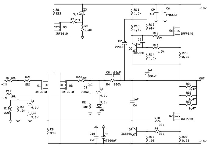
Please note not all components can be found on PCB! C6, C7, C9 and C10 are part of the power supply. 47000uF is just a recommended minimum value for one channel, can be increased as much as possible - don't forget, is a Class A amplifier (parallel connection of capacitors with low ESR value)! Z4 and Z5 also were neglected from PCB, because in the normal case can not come extra voltage from the output to damage Q2. C4 and C5 are also to prevent the self-oscillation of the circuit. Can be mounted (in SMD package) just if are needed. In symmetrical operation can be used R1 & R17; and R3 & R19 not needed. In asymmetrical operation, R3 is replaced with R19, and R17 is not needed. The role of R7, R16, R18, R21, and R23 is to prevent parasitic oscillations in MOSFET. Their role is not significant in the case of Q1 and Q2, but for the rest it is.
The Hiraga amplifier
The above-presented amplifier was published in the l'Audiophile No. 15 by Jean Hiraga & Gérard Chrétien and is known as The Hiraga amplifier, a famous class A example. The PCB and the component placements can be seen here (consider, that PCB was designed by Hiraga for schematic published in l'Audiophile No. 10, for that reason the components value is different, but the circuit is nearly same). Note: the recommended bias current can be between 0.8-2.2A (Hiraga recommending 0.8-1A, but with 2A sounds better!).
Connected design ideas:
- Power filter and power delay circuits for amplifiers protection