Amplifier grounding
Good grounding in equipment is essential for their good performance. Most problems with noise like hums, buzzes, interference or cross talk usually are caused by bad grounding. Ground signals carry currents and currents through wires or PCB routes cause voltage drop. Any difference in voltage between 2 ground points will cause current flow and this will cause some sort of problem. These currents that flow through the different grounds are well known as ground loops. Almost everybody who has worked with audio equipment and installations knows how hard it is to solve problems like this. In the following article you can read some info and guidelines of how to successfully ground your amplifier or any other equipment.
Ground in electronics (as Earth in electrical installations) is a reference voltage point for all signals equal to 0 Volts. It is a general rule that ground signals must be kept apart. A reference ground point called Star point should be defined in the design phase and all ground tracks must return here separately. All ground tracks must have the lowest resistance possible with thick wires, wide tracks on PCBs and so on.
The requirements that should always be met when designing or wiring an amplifier are in general the following:
- There should be a Star point as a reference for all signals.
- In stereo amplifiers the grounds must be separate for good cross talk performance.
- All unwanted AC currents (not audio) in the amplifier must be kept away from the audio signal ground. The input ground and feedback ground must be kept clean from any other signal. Any voltage difference between these 2 grounds will appear directly in the output.
- The large charging currents from the big electrolytic capacitors of the power supply must be kept away from all grounds. These currents are big and can be picked up very easily. These are the cause for bad performance in a lot of amplifiers which are otherwise excellent designed. So be very careful with this part.
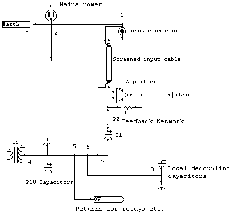
A very good wiring example of an amplifier can be seen in the following schematic.

Noise and interference can get into the amplifier from two places in general. The mains power plug and the input connectors. From the first any kind of interference from the outside world through the power cables and the second usually ground loops that are formed from the grounds of different equipment. The solution is to connect the mains ground to the chassis ground through a protected earth and the chassis ground directly to the input connector. In this way ground loops must flow through 1-2 to the Protected Earth at 2 and then to mains ground through 2-3. This is the best topology to avoid ground loops even when not using balanced inputs. Also you can see that the capacitor charging pulses stay in the connection 4-5 and don't flow through 5-6. In 5-6-7 there is also ripple that is carried back from the power supply decouple capacitors near the amplifier but it stays out of the ground path 1-7 that is the most sensitive.
Usefull links
How to Wire-up an Audio Amplifier - by Andrew C. Russell. Is a good article about preventing hum and noise problems in audio amplifiers.
Grounding - by Merlin Blencowe. Is the 15th chapter of a famous book: Designing Tube Preampls for Guitar and Bass
Grounding and reducing noise, hiss, hum and buzz - from Electro-Dan homepage. Contains tips, how to ground correctly, how to make a "groundbreacker"
Audio Component Grounding and Interconnection - by David Davenport on diyaudio.com forum. Is a detailed grounding "procedure" for single and balanced systems.
Earthing - from Elliott Sound Products homepage. Contains usefull information about safety, grounding and ground-humm reduction