Power filters and delay circuits
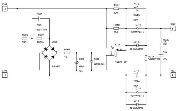
On the next figures are presented a mains DC filter and a power on delay circuit. This is inserted between the power switch (and the mains filter) and the mains transformer (primary side). C313 and C314 (both 2200uF/25V) with the diodes in parallel makes the DC blocking filter. The components 303-309 reduce and rectify the mains voltage with a slight delay, in such a way that the relay (24V) is shortening the resistors R311 and 312 (both are 220/10W) after a few ms. Note: resistors value can be setted separately for each applications. The voltage at the output will increase gradually, protecting the transformer and the amplifier's power capacitors from power on "short" effect. With that the large current inrush is avoided when the amplifier is switched on. The varistor R319 is attenuating mains transients, while the components 320 (10/6W) and 321 (47nF/400VAC or 630VDC) provide for additional filtering.
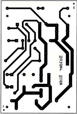
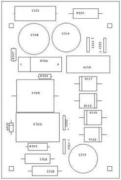
The circuit laid out on a small printed circuit board, measuring about 95x65 mm. The layout (notice that this is mirrored)
An other famous delay circuit published in Elektor (famous, because you can find it in several webpages):
This also can be connected directly between mains filter an power switch. It’s not obligatory to use one but it is a good idea, especially if you have a big toroidal transformer, larger than 300 VA (for transformers below 300 VA you can increase the values of resistors R4-R7, for ex. 15 or 24 ohms) and a few hundredthousand microFarad capacitors in secondary part. This unit has a delay circuit and for the delayed time the mains power is supplied through power resistors minimizing in this way the big inrush current due to big capacitors and big toroidal transformers in the power supply. When everything is stable it shorts the power resistors and supplies the mains power directly.
In the following schematic you can see the circuit. It’s very simple and don’t needs additional supply.
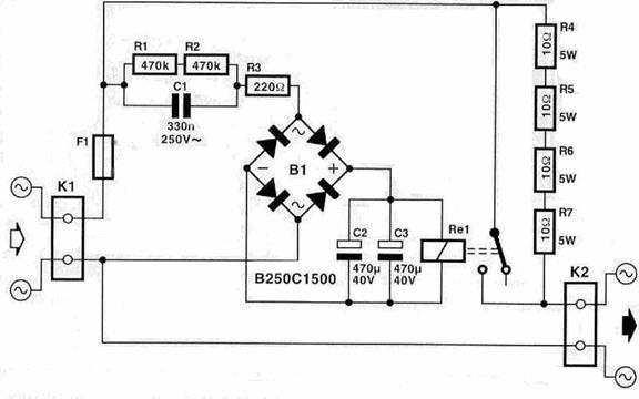
The inrush current is suppressed down to 5.5A through the resistors R4-R7 right after power up. After the delay time that is determined from capacitors C2 and C3 the relay shorts the resistors and all the current is supplied to the transformer. The relay in this circuit can work with toroidals till 2000 VA. The voltage for the supply of this circuit comes directly from the mains power supply through C1, R3 and B1 so it is very dangerous to touch this part of the circuit.
In the picture below you can
see what the PCB looks like. 
The finished circuits picture:
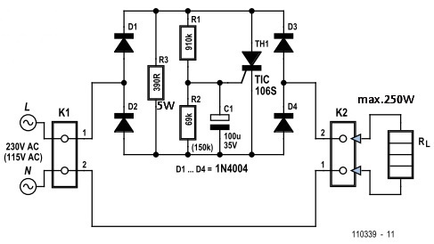
The best and simlest circuit can be seen on the next schematic. Appeared in Elektor 2012/7-8. The author use tiristor instead of triac, because of different trigger sensitivities for positive and negative half-waves. Limitations: can be used with components marked till 250W. Above should be changed the tiristor, the diodes, the values of R3 (for short period is connected in series with the load) and eventually the value of R1 based on gate current of tiristor. The starting time can be extended increasing the value of C1.