Speaker protection
Every hi-fi amplifiers have some protection circuits, either to protect the speakers from an amplifier fault, and/or vice versa. Some of these are implemented at a very basic level - for example the use of a fuse, but some of them use quite clever circuits. The basic requirement of a speaker protector requires that any potentially dangerous DC flow to the speakers should be interrupted as quickly as possible - fast enough to stop the loudspeaker drivers from being damaged.
The presented schematic was published by Rod Eliot on his website as Loudspeaker Protection and Muting. I did not would like to repeat in details the full project, you can find it on Rod's page, he explains the principles, and shows a suitable detection method that may be applied.
The circuit includes: DC protection, a mute function, AC or power detection and can be extended with thermal protection. The mute protection leaves the speakers disconnected until the amplifier has settled, and disconnects the speakers as quickly as possible after power is removed to prevent the turn-off noises that some amplifiers, especially those which haven't output capacitor, generate.

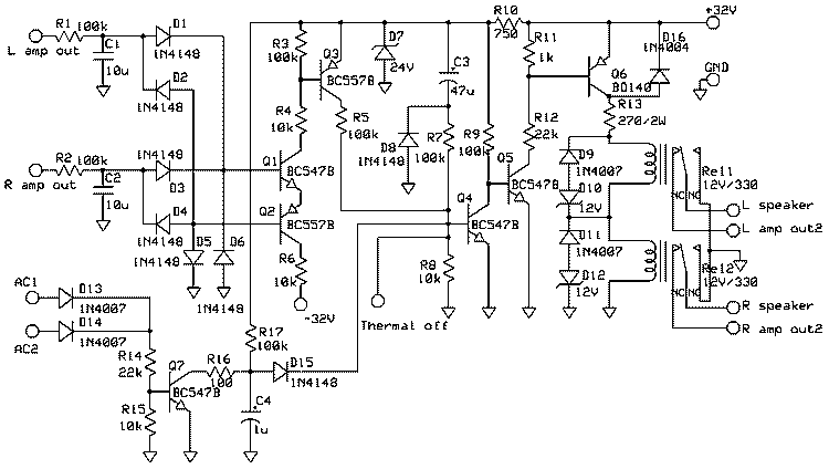
Figure 1 The schematic of speaker protection circuit
The input is a DC detector/filter with 1s time constant, but in 50ms can turn off the relay if a DC voltage appears on it. C1 and C2 must be non polarized capacitor - I use 10uF PE.
The second part is the relay activation circuit - this can collect all error signals from DC detector, from muting or thermal protection. Because this circuit is mounted into an amplifier with +-32V voltage (used for B5 power amplifier), I use 2 pcs of 12V relays in serial connection. R10 and R13 can be recalculated in function of used power supply. Through R10 flows 10mA (R10=(Vsupply-V24)/10mA=800 ohm, selected 750 ohm resistor), and through R13 the relay activation current (=Vrelay/Rrelay), R13=(Vsupply-Vsumrelay)*Rrelay/Vrelay=8*330/12=220. Please consider also the power dissipation and select the right wattage resistor (Pr=Vr^2/R)! In case of R10 the power dissipation is less then 0.1W, but in case of R13, the power is approx. 0.3W (I selected a 2W resistor). D8 discharges C3 if the supply collapses or are swithed off. It will not help much in the case if the power are switched off and back on, but can reset the circuit much faster than would otherwise be the case. Vec of Q8 are protected with D16 from reverse voltage generated by relays coils, anyway limited by D9-D12. When power is removed from the system, the relay will open to stop turn-off transients from being heard. Likewise, the system will be muted for about 2 seconds after power is applied to stop the turn-on transients as well. C3 and R10 in the circuit of Figure 1 provide the turn-on delay, by supplying current to the "Off" terminal as C3 charges. Once charged, the current falls to zero, and Q4 turns off, allowing Q5 and Q6 to turn on, energising both relays. The power detector cannot run from the DC supply, as this may take a considerable time to collapse. The common approach is to use a rectified but unsmoothed output from the transformer secondary. Because it is not smoothed, this disappears instantly when power is removed, and is ideal. The circuit simply uses the current pulses to keep the C4 capacitor discharged via Q7. When the pulses stop, the cap charges until the threshold voltage of the "Off" terminal is reached (0.65V), and the relays are turned off. After power is first applied, the timer circuit will activate the relays after about 4 seconds. Both relays with their protection diodes (D9-D12) are monted directly on speaker output connector, not on PCB, to shorten the audio signal path.

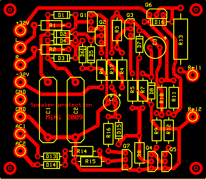
Figure 2 The pcb from components side

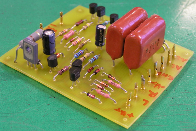
Figure 3 The finished protection circuit