RIAA preamplifiers

Analog recording till now is not dead, some famous makers appearing with better and better turntables (like Teres, Denon, Seiki, TEAC, AudioTechnica, Technics and some names from consumer audio, like Panasonic, Sony etc). Why? Please read the article about CD recording!
The MC RIAA preamplifier
At first, we can have 3 main criteria for a good MC preamplifier:
- to be noiseless as much as possible,
- to keep between certain limits the deviation from RIAA curve, to have the right designed networks,
- to have sufficient amplification to drive an amplifier.
Some years ago, I saw already this circuit in an Elektor magazine (was republished also in the Hungarian edition in 1991 nr. 2 pages 6-9.), but at beginning of 2005 one of my "high-end" friend, focused my attention again on it. I listen to it at his home, and I was completely astonished, the sound was great, marvelous, much better than a CD (Decca) made from the same recording!
Some parameters of
this moving coil (MC) preamplifier:
- Nominal input level 0.25mV,
- Input impedance: 100 ohm,
- Output at 1kHz: 200mV
- Output impedance:
2kohm,
- S/N ratio 75 dB,
- Deviation from RIAA curve <0.1dB,
- THD <0.006%
- Required current:
24mA on 15V sym. (0,72W).
Having symmetrical input, the cartridge is coupled directly, without capacitors!
The schematic:
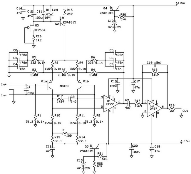
The first stage (Q1a and Q1b) is a differential amplifier made with Analog Devices' low noise matched dual PNP transistors MAT03 (0.7nV/ Hz). The very low noise is achieved using a 4 mA current source made with Q2 (2SA1015).
The cartridge is symmetrically connected, without coupling capacitors, eliminating the distortion and frequency dependant delay produced by them - but that stage can be built very carefully. For that reason the first stage is powered through 2 filtering circuits made with Q4 and Q5, eliminating the noise (brum) provided via supply voltage.
C1 value is critical and depends on what type of cartridge is used. For AudioTechica OC9 270pF with listening test was perfect (just in my case, because this depends on the cables used till the input of premplifier).
To increase the common noise reduction, in the differential stage both networks (R3, R5, C2, C3, C4 and R4, R6, C5, C6, C7), also the feedback, can be the same! That means all components' tolerance must be lower than 1%!
With P1 the offset voltage of the differential stage can be adjusted to 0 V, to have perfect symmetry. In that way, the DC voltage can not go through the preamplifier, and can't "heat" the cartridge. The next is a 20Hz high pass network made with C9R17. C9 values can be increased, decreasing the cut-off frequency below 20Hz, but can be higher than the margin of the rumble of turntables chassis' self-frequency. I also heard good results with 15uF, with powerful and live bass - but as I mentioned earlier, not any system can accept such low cut-off frequency, depending on the whole system (resonance frequency of arm, chassis, cable, RIAA, power amplifier and finally by speaker system). Please be careful, because the rumble with resonance can destroy your speakers!
The U2 is the second amplifier, in a feedback network with a 2120Hz high pass filter (C10R18). With those values, the deviation from RIAA curve is <0.05%! The last resistor protects the preamplifier from oscillation in case of capacitive load.
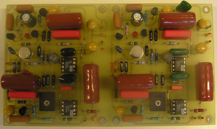
Differences from original schematics: when I built it I use transistors 2SA1015, 2SC1815, 2SK30A (instead of BF245A), and AD797. Power line capacitors are mostly tantalum-type. Later I recognized, that the sound of AD797 is too boring, and I changed some components. Now in the final version, I use the original transistors (try to find NOS Philips) BC546-556, because their sound character is better, and as an operational amplifier I recommend OPA1611 - but is better if you find your opamp, which fits in your system configuration.

All components were selected very carefully, all tolerances are more accurate than recommended ones in the original Elektor's article. The most difficult was to find 4 capacitor blocks (in a total of 12 capacitors) with the same 955nF/block values - for this reason, they look so different on PCB. Recommendation: is better, if the capacitors are from the same manufacturer/same dielectric materials. If is made from a different dielectric, the result rarely can be better. The picture shows a previous version when I try to find the optimal sound.
The MM RIAA preamplifier
I have a few turntables, and the next circuit are used for a Pioneer PL200, which is equipped with AudioTechica AT95 MM cartridge - for this reason, I decided to build a MM preamplifier for it.As background, I read several articles on the net or in specialized magazines or books, but the best one was the Product Review Budget Phone Preamps by Charles Hansen and John and Sandra Schubel in AudioXpress 4/2003, page 40-56. In conclusion this article, supported by their listening test and measurements (compared with original specifications), the best preamp based on the author's opinion was the Bugle made by Hagerman.
On Hagerman webpage can be found an updated version (in Budget2 just the power part was modified, but the RIAA network and opamp circuit remain the same, the newest version, the Budget3, contains additonal switches to select between MM/MC cartridge, adjusting the gain and the input impedance)- but in case of MM should be selected also the input capacitor, considering also the capacitance of the cable from cartridge till preamplifier input.
Below you can see the schematic:
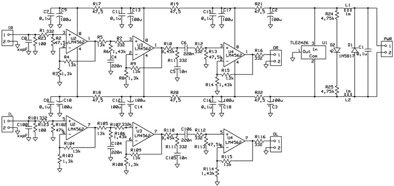
The first stage boots the magnetic cartridge signal by 21dB. The 3 steps RIAA curve is implemented in 2 passive EQ stages (are not used feedback or other active EQ). The RC network between U2 and U3 provides the 3180us and 318us breakpoints. The RC network after U3 provides the75us breakpoint. An additional series RC before U4 adds a low-frequency -3dB roll-off 15Hz, and removes the DC offset passed from the first 2 stages.
Remark: RIAA circuits with passive EQ may clip a bit at the high frequencies because of the high gain required from the input stage, coupled with the rising cartridge output with frequency. By distributing the gain over 3 stages, this preamplifier avoids this problem.
Some parameters of
this moving magnet (MM) preamplifier:
- Gain: 40dB (or 60dB, fixed), measured 40dB
- Input impedance: 47kohm + 14pF, measured 48.5kohms at 1kHz
- Output impedance: 330 ohm, measured 307 ohm
- Distortion: <0.05% from 30Hz to 60KHz, measured 0.03%
- Bandwidth (-3 dB): 15Hz to 150kHz,
- S/N ration 74 dB ref 5mV A-weightened, measured 72dB
- Deviation from RIAA
curve <+/-0.5dB at 1kHz, measured +/-0,6dB
- Overload: 55mV at 1kHz
- measured Crosstalk at 10kHz: -62dB
- max DC offset mesured +6mV
Listening opinion: no audible noise or hum. Instrument details are excellent, very clear, with impressive details at midrange.
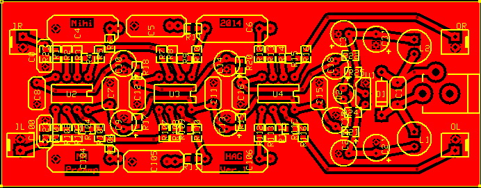
Below you can see the PCB (I try to keep Hagerman components placements to have an almost similar pattern):
Other interesting RIAA preamplifiers:
1. MC phono input published on the net by Andreas Hunnebeck as AH PRE-1 Highend Preamplifier.
2. A MC preamplifier by Ernő Borbély published in The Audio Amateur 4/86: Part 1, and Part 2.
3. All jfet MM/MC phono preamplifier by Ernő Borbély published in audioXpress 6/05: Part 1, and Part 2.
4. PASS Laboratory's MM/MC phono preamplifier: Pearl Phono Stage
5. Another low noise
MC phono preamplifier published in Elektor 12/98: MC
low noise preamplifier
Connected design ideas: