Radio receivers
My hobby also covers wave-surfing, but not as a radio amateur, just as a DX-er, mostly on FM (regarding its higher quality), but also on medium and short waves.
If we examine the development of radios over time, we can say that until the early 1980s, well-known brand manufacturers (such as Philips, Marantz, Dual, Denon, Sony, Onkyo, Kenwood, JVC, Pioneer/Technics, etc.) aimed to produce equipment of an incredibly high quality. After that, any air radio wave reception equipment, like radios/tuners/receivers degrades, especially on AM bands. If you buy a radio today for on-air bands, you will encounter low-quality audio (the compression used by DAB, DAB+, and the internet, only theoretically achieves the FM stereo signal quality, in reality, is less listenable), as well as low-quality receivers/tuner parts (sensitivity decreased, or now the conversion are using DSP circuits instead of linear or PLL ones). Since the 1990s, the LW and MW have been neglected (as well as the SW, but this was popular in the Far East/Japan, America, etc.). As a result, receiver sensitivity on LM and MW has decreased from 8 uV to a few hundred uV-s, forcing consumers to use only FM/DAB, which has a smaller coverage area but marketed as better reception quality. The importance of FM radio is beginning to decline as internet radios (which stream signals that have been coded or packed) become more prevalent. There are more and more DAB/DAB+ capable receivers on the market right now, but without stations that can broadcast such programming in high quality, I don't think this will be a success story. Based on the European Parlament decision: since 1st Jan 2021 new automobiles sold in the EU must have multimedia on board with DAB reception possibility.
Regarding sound, analog radios are my preference, but I'm also curious about emerging technology in this area. Due to this, I collected a number of radios and receivers, starting with those that belonged to my great- and great-grandparents and continuing up to modern PLL digital tuned receivers with DSP conversions and DAB capability. Most of the time, I refurbish them by replacing worn-out parts to maintain peak radio and audio performance.
Some words about FM band:
The FM broadcast band is a range of radio frequencies used for FM broadcasting by radio stations (Wikipedia). It runs from 87.5 to 108 MHz in Europe, Africa, and Australia (also known as CCIR). Japan's FM broadcast band ranges from 76 to 95 MHz. Eastern Europe's International Radio and Television Organization (OIRT) spectrum spans 65.8-74.0 MHz. As in the case of Russia, these Eastern European nations currently largely utilize the 87.5 to 108 MHz range, while some of them have already switched from the OIRT spectrum to the CCIR band.The FM bandwidth in Europe was first available between 87.5 to 100 MHz (the first FM transmission in Europe began in the Netherlands in 1953), and this was extended in 1968 to 104MHz, and since 1979 to 108MHz. Due to this reason, some vintage radios' produced before 1980 have the coverage of FM from 87.5 to 100MHz (radios with tubes) or to 104MHz (manufactured with semiconductors), like in the case of old DUAL, ITT, or WEGA tuners/receivers.
Channel spacings:
- Since 1984, the majority of countries have adopted channel spacings of either 100 kHz (for all of the EU, excluding Italy) or 200 kHz (for the USA). Some FM radios with digital tuning are not able to tune in increments of 25 kHz, 50 kHz, or even 100 kHz. As a result, it may be difficult to properly hear stations that use such increments when traveling abroad. An analog-tuned radio won't be affected by this issue in terms of reception.
- Some countries, like Italy, have severely congested FM bands, yet permit a station to operate on any multiple of 50 kHz anywhere it can fit. The 50 kHz channel spacings take advantage of the capture effect and receiver selectivity of FM to assist in preventing co-channel interference.
- The OIRT norm permitted steps of 10kHz, although this does not imply that the channel spacings were exactly 10kHz. This separation probably allowed for better use of the band without interference because the utilized frequencies were not very crowded.
There is greater noise during FM modulation transmission at higher audio frequencies than at lower audio frequencies. The broadcasting industry developed some guidelines for Pre-emphasis and corresponding De-emphasis to correct for this imbalance and even out the noise across the audio spectrum. Pre-emphasis is used in a modulator to enhance the audio before modulation. After demodulation, the receiver employs de-emphasis to restore a flat audio frequency response. As a result, the Signal-to-Noise Ratio of any particular FM transmission technology is greatly enhanced. The FM radio de-emphasis standard in Europe is 50 microseconds, while it is 75 microseconds in the USA.
Some words about DAB (Digital audio broadcasting) radio:
Digital audio broadcasting (DAB) is a digital radio technology for broadcasting Digital audio radio services, used in several countries across Europe and the Asia Pacific.DAB may offer more radio programs over a specific spectrum than analog FM radio. DAB is more robust with regard to noise and multi-path fading for mobile listening since DAB reception quality first degrades rapidly when the signal strength falls below a critical threshold, whereas FM reception quality degrades slowly with the decreasing signal.
Audio quality varies depending on the bit rate used and the material. Most stations use a bit rate of 128 kbit/s or less with the MP2 audio codec, which requires 160 kbit/s to achieve perceived FM quality. 128 kbit/s gives a better dynamic range or signal-to-noise ratio than FM radio, but a more smeared stereo image, and an upper cut-off frequency of 14 kHz, corresponding to 15 kHz of FM radio. However, "CD sound quality" with MP2 is possible just "with 256...192 kbit/s" - which remains a dream using DAB.
An upgraded version of the system was released in February 2007, which is called DAB+. DAB is not forward compatible with DAB+, which means that DAB-only receivers are not able to receive DAB+ broadcasts. However, broadcasters can mix DAB and DAB+ programs inside the same transmission and so make a progressive transition to DAB+. DAB+ is approximately twice as efficient as DAB due to the adoption of the AAC+ audio codec (HE-AAC version 2 audio codec, or 'aacPlus'), and DAB+ can provide high-quality audio with bit rates as low as 64 kbit/s (but will never achieve CD-s quality). Reception quality is also more robust on DAB+ than on DAB due to the addition of Reed-Solomon error correction coding. DAB uses a wide-bandwidth broadcast technology and typically spectra have been allocated for it in Band III (174-240 MHz).
Hungary has chosen DAB+ for its digital radio standard. On 23 January 2009 Antenna Hungaria started experimental broadcasting on its DAB+ digital terrestrial radio network on one channel: 11D. From 3 January 2011, with 7 available radio programs within the frames of the experimental DAB+ broadcasting in Hungary:
- Kossuth (stereo 80kbit/s),
- Petofi (stereo 112kbit/s),
- Bartók Rádió (stereo 128kbit/s),
- Magyar Katolikus Rádió (mono 64kbit/s),
- Klubrádió (mono 48kbit/s),
- Lánchíd Rádió (stereo 64kbit/s),
- Inforádió (mono 48kbit/s)
The DAB+ transmission was stopped in Hungary at 12.09.2020.
Below you can see my radios collection by manufacturers in chronological order.
Manufacturers
- Aiwa: XT003
- Akai: AT-2400; AA-1015PL
- AOR: AR-3000A
- Audion: T 6800 (Rosita T6800/T6500, Innerein RT6500)
- Blaupunkt: RX+ 12
- Dansk: T-3535
- Denon: TU630; TU747; TU1500RD; TU1500AE
- Dual: CT-1250; CT1450; CT1640; CR1780
- EduTec: LT9095
- Fisher (Sanyo): Studio-Standard FM-2310; Studio-Standard FM-58
- General Radio Co.: 419-A
- Grundig: T7500; Satellit 400; Satellit 700; Yacht Boy 360; Yacht Boy 400 old; Yacht Boy - Porsche 2000; WR5401 - Yacht Boy 10
- Harman Kardon: TU-9600
- Hitachi: FT-340; FT-3500; FT-8000
- JVC: T-X1L; T-K10L
- Kenwood: KT-815; KT-80; Basic T2; KT-880DL; KT-5020L; KT-1050L
- Luxman: T-4
- Marantz: ST-450; ST-530; ST-64L; ST-6000
- NAD: NAD 4220
- Nikko: Nikko STA7070
- Nokia: RP-9160 (Sangean ATS-808)
- Nordmende: TU-1300
- Onkyo: TX-2500; T-3100; T-4210R; T-4211; T-4970, T-9060
- Optonica (Sharp) -> see Sharp
- Panasonic: RF-9L; RF-B20; RF-B45; GX500/RF3500; RF-U350
- Philips: L1W35T; FT920; FT930; FT980
- Pioneer: F-90; F-77
- Radiopribor: Meridian RP-248
- Realistic/Radio-Shack: Pro-29
- ReVox: A76
- RFT: Capri 6401 Stereo
- Rotel: RX-850
- Saba: TS2030 RDS
- Sangean PR-D1; ATS-909; ATS-909X; DT-220; DPR-69+; (ATS-808 -> Nokia RP-9160; SG-789 -> Siemens RK-621; PT-633 -> Siemens RK-747)
- Sansui: T-500L
- Sanyo: FMT-30L; FMT-611 (Expert 1640)
- Sharp (Optonica): ST-1122H, ST-1616H
- Siemens: RH-777; RH-300; RK-621 (Sangean SG-789); RK-747 (Sangean PT-633)
- Sony: STR-7055A; STR-4800; STR-232L (Wega PSS-200R); ST-JX3L; ST-J60, ST-SE500; ICF-2001D; ICF-7600AW; ICF7600D/ICF2002; ICF-7601; ICF-SW7600; ICF-SW30; ICF-SW7600G; ICF-SW11; ICF-SW7600GR; XDR-S40D; XDR-S41D,
- Technics: SA-5370; SA-80; ST-Z1; ST-G5; ST-G3S; ST-G450
- TechniSat: Viola 2 C IR
- Tecsun: R-9701
- Telefunken: 076WK; RT300; HT660; HT850; HT990 RDS
- Tento: Selena B-211; Selena B-215; Selena B-216; VEF-214; VEF-222; Spidola / VEF 242
- Terta: Orionette 1004
- Tivoli Audio: Model One; Model Three
- Tungsram (Dansk) -> see Dansk
- Uher: EG750
- Unitra: AS-630, AS-631B
- Videoton: RT 7300 S
- Wega (Sony): JPS352 SE T; T120L (same as Sony ST-A30L); PSS-200R (see at Sony STR-232L)
- XHData: D808
- Yamaha: R-3; R-700; T-700
Aiwa
The company was founded on June 20, 1951, as AIKO Denki Sangyo Co., Ltd., manufacturing microphones, and changed its name to Aiwa Co., Ltd. on March 10, 1959. The company was a leading manufacturer of audio products, including headphone stereos, minicomponent stereo systems, portable stereo systems, minidisc players, CD, and cassette players, and car stereo systems throughout the 1970s, 1980s, and 1990s. Nearly 86 percent of company revenues were derived from such audio products.
Aiwa manufactured more than 89 percent of its output outside Japan, with a heavy emphasis on the lower-cost South-East Asian nations of Singapore, Malaysia, and Indonesia. The company was also heavily dependent on overseas sales, with more than 80 percent of total revenues being generated outside Japan, with 43 percent in North and South America, 25 percent in Europe, and 13 percent in areas of Asia outside Japan and in other regions.
Although not then officially an affiliated company of consumer electronics giant Sony Corporation, by 1982, Sony had a 54.6% stake in the company, effectively giving it majority control. With growing competition throughout the late 1990s, the company slid towards bankruptcy, and the troubled company was then fully purchased by Sony Corporation in 2003. However, the new direction of Aiwa under Sony did not meet consumer and sales expectations. On January 21, 2005, new product development ended, and by 2006, Aiwa products were discontinued and no longer sold in the market. Sony announced the termination of the brand entirely on May 14, 2008.
Aiwa XT003
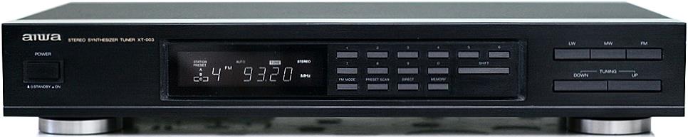
General information:
- Digital 3 band PLL tuner (superheterodyne)
- Frequency range: FM 87.5-108 MHz, MW 522-1611kHz, LW 144-290kHz
- Usable sensitivity: 0.9uV on FM mono, 300uV/m on MW and 1000uV/m on LW
- Tunning steps: LW 3kHz, MW 9kHz, FM: 25kHz
- Preset memories: 30, mixed for AM and FM
- Used integrated circuits: AM/FM tuner and IF: LA1265G, MPX decoder: LA3401, PLL frequency synthetiser LA7218, microcontroller and display driver LC65148-4431, voltage regulator 78M12L
- Antenna: for FM 75 ohm unbalanced, for AM loop antenna or aerial
- Signal to noise ratio: FM 80dB in mono, 74dB on stereo, AM 52dB
- Total harmonic distortion (1kHz): on FM 0.12% in mono, 0.2% in stereo, on AM is 0.5%
- Alternate channel separation: 70dB on FM, and 20dB on AM
- Stereo separation: 40dB at 1kHz
- Frequency response: 30-15kHz, +0.5...-2dB
- Output signal level: 700mV on 47Kohm
- AM (MW) suppression ratio: on FM 50dB
- Power source: 220Vac, 50Hz
- Power consumption: 7W
- Dimension: 430 x 73 x 255 mm (W x H x D)
- Weight: 2.5 kg
- Original price at 1992: 350 DM
Good things:
- Is a 4 gang tuner on FM with a good sensibility
- The sound at AM reception is clear, low background noise
- Has a Preset Scan mode: will scan the stored programs
- Very clear display with good intensity, and can be seen from a wide-angle!
Problems:
- The IF bandwidth cannot be selected (ex. normal and narrow)
- No signal meter, just a Tune mark on the display
- In stereo mode, the manual search is canceled, which means will stop just on stations with a high signal level
Upgrades:
- All electrolytic capacitors changed
- Modification:
- Audio path: all capacitors are PP, on the output (C69 and C70) were increased from 2.2uF to 4.7uF. On the output board, the ground capacitor was changed from 0.01uF ceramic to 0.1uF PP and the 2 noise-canceling to 220pF COG ceramic.
- Power path - mentioned just the modified values, voltage ratings remain same or higher: C33 390uF, C61 470uF, C75 390uF, C80 390uF, C83 390uF, C85 100uF, C88 4700uF, C91 100uF, C94 330uF, C206 0.22F, C205 470uF (in some places I mounted solid electrolyte capacitors or tantalum, below 1uF PP type).
- AC line input get an EMI filter formed with 1uF + 2x27mH coil + 1uF
Akai
Akai was founded by Masukichi Akai and his son, Saburo Akai as Akai Electric Company Ltd. (Akai Denki Kabushiki Kaisha), a Japanese manufacturer in 1946. Akai's products included reel-to-reel audiotape recorders (such as the GX series), tuners (top-level AT, mid-level TR, and TT series), audio cassette decks (top-level GX and TFL, mid-level TC, HX, and CS series), amplifiers (AM and TA series), microphones, receivers, turntables, video recorders, and loudspeakers. Many Akai products were sold under the name Roberts in the US, as well as A&D in Japan (from 1987 after a partnership with Mitsubishi Electric), Tensai and Transonic Strato in Switzerland and Western Europe (until 1988). During the late 1960s, Akai adapted Tandberg's cross-field recording technologies (using an extra tape head) to enhance high-frequency recording and switched to the increasingly reliable Glass and crystal (X'tal) (GX) ferrite heads a few years later. The company's business eventually became troubled and it left the audio industry in 1991. Akai Holding filed for insolvency in November 2000. It emerged that ownership of Akai Holdings had somehow passed in 1999 to Grande Holdings, a company founded by Akai's chairman James Ting. In early 2003, Grande Holdings began undergoing a re-exposure of Akai's brands by marketing various audio-visual products manufactured by Samsung.
Akai AT-2400
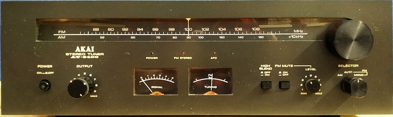
Is a middle-grade receiver made between 1976-1976 in Japan by Akai Electric Co, Toho. Was made in 2 versions: with a silver front and brown wood cabinet, and with a black front and wood cabinet. The difference between the top model, AT-2600, is the AGC of the front stage full with MOSFETs, has 5 gangs on FM, 3 on AM, and the signal meter can be switched to show the deviation (distortion) of signal, which gives a more precise adjustment of received station by the tuner.
General information:
- Analog 2 band receiver
- Coverage: FM 88MHz - 108MHz, AM 520kHz - 1605kHz
- Sensitivity: for FM 1.8uV (no data for stereo); for MW 180uV/m with bar antenna and 15uV with external antenna
- No presets
- Signal to noise ratio: 75dB on FM in mono and 70dB for stereo, and better than 50dB on AM
- Harmonic distortion: less than 0.2% on mono, and less than 0.3% on stereo FM
- Image rejection: more than 90dB at 98MHz
- IF rejection: more than 100dB at 98MHz
- Spurious rejection: more than 100dB at 98MHz
- Muting level control: 5uV to 100uV/switchable ON/OFF
- AM suppression: 55dB
- Stereo separation: more than 45dB
- Subcarrier suppression: more than 65dB
- Antenna input impedance: 300 ohms balanced, 75 ohms unbalanced, for AM external and ground connection via screw type connection, or built in ferrite bar for AM
- Used integrated circuits: AM tuner and IF: uPC30C, FM IF: LA1230, MPX decoder: LA3350, operational amplifier LA3122 (for output audio buffer)
- Output audio bandwidth: 20 - 15kHz with +0.2dB...-1.5dB
- Output signal level: Variable between0...1.6V, Fixed 0.77V/1 kohm (100% modulation
- Power: 220Vac, 50Hz
- Dimensions/weight: 440 x 141 x 335 mm (WxHxD)
- Weight: 6.6 kg
- Price at 1977: 648 DM
Good things:
- Very clear and pleasant sound, is better than Marantz or Dual from same era
- Separate audio buffer IC at the output
- Adjustable and fixed audio outputs with RCA sockets
- Adjustable and switchable muting for FM
- Simple and classic design with white backlight
Difficult, problematic items:
- Backlight bulbs are difficult to be found on the market, no any marks on them, are powered from 10.3Vac. In the AT-2600 service manual are mentioned bulbs are same with AT-2400 model, and is 8V/300mA type, which is high overpowering/shorter life for bulbs.
- No datasheet can be found about uPC30C integrated circuit
Always, when I start to repair, refurbish or upgrade one tuner, I check the upper version of that product range. In this case, the AT-2600 model schematic was checked. Pin 10 of IC1, uPC30C, is connected to the ground via 4.7uF/35V and to +5.9V via an 82kohm resistor. Also, the C12 was replaced with 0.1uF (AM audio output), and R7 with 100kohm.
Power board: C4 changed to 2200uF/35V, C5 and C9 to 470uF/35V, C6 and C8 to 330uF/16V dry electrolyte capacitor.
Front end/AM board: C8 changed to 270uF/16V, C8 and C13 47uF/16V - all of them with dry electrolyte capacitor type.
Main board: C33 to 470uF/35V Rubycon, all audio related capacitors changed to Nichicon Fine Gold or Muse type, same values.
The tuner supply from the secondary of the power line transformer received an EMI filter formed with 2x1uF/100V pp type and noise canceling coil 2x6.2mH.
Bulbs replacement: each bulb was replaced with 3 warm white LEDs in series connection, in parallel with them received a 10uF/25V MLCC capacitor and 2 of 62 ohms resistors used as terminals - all 4 assemblies connected in parallel to 10.3Vac of power transformed 2-2 reversed, to have an uniform loading in + and - cycles.
Akai AA-1015PL
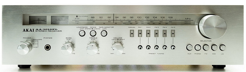
Is a middle-grade receiver made between 1977-1979 in Japan. Is the varicap version with presets of the AA-1010L model, previous model was the AA-1010DB started one year earlier, in 1976.
General information:
- Analog 2 band receiver
- Coverage: FM 88MHz - 108MHz, AM 520kHz - 1605kHz
- Sensitivity: for FM 2uV (no data for stereo); for MW 200uV/m with bar antenna and 20uV with external antenna; for LW 300uV/m with bar antenna and 30uV with external antenna;
- 5 presets just for FM via touch sensors
- Signal to noise ratio: 65dB on FM and >45dB on AM
- Harmonic distortion: 0.3% on mono, 0.6% on stereo FM
- Antenna input impedance: 300 ohms balanced, 75 ohms unbalanced
- Used integrated circuits: AM tuner and IF: uPC30C, FM IF: LA1230Z, MPX decoder: LA3350S, touch switch controller: uPC1009C, operational amplifier LA3122 (for RIAA)
- Output: 15W/channel on 8 ohm
- Signal to noise ratio: Phono >75dB, AUX >90dB
- Power bandwidth: 40 - 20kHz with 0.8% THD
- Channel separation: better than 50dB on from Phono at 1kHz
- Residue noise measured at the output on 8 ohms load: 0.8mV
- Damping factor: more than 30 at 1kHz on 8ohm
- Input sensitivity and impedance: Phono 3mV/47kohm, AUX 150mV/100kohm
- Tape monitor: input pin/DIN 150mV/100kohm; Output pin 150mV/2kohm, DIN 30mV/30kohm
- Frequency response: Phono/RIAA 30 - 15kHz +1dB...-1dB, Tuner/Aux/Tape monitor 10 - 70Khz 0..-2dB
- Tone control: Bass +-10dB at 100Hz, Treble +-10dB at 10kHz
- Loudness control: +10dB at 100Hz, +5dB at 10kHz (volume control set at -30dB position)
- Power: 220Vac, 50Hz
- Dimensions/weight: 440 x 125 x 265 mm (WxHxD)
- Weight: 6.2 kg
- Price at 1977: 600DM
AOR
AOR, Ltd. (Authority on Radio Communications, Ltd.) is a Japanese based manufacturer of radio equipment, including transceivers, scanners, antennas and frequency monitors.
Established in 1977 when two radio amateurs decided to go professional. Based in Tokyo, Japan, they also have offices in the United Kingdom and the United States, and manufacturing facilities in Japan and the United Kingdom.
AOR AR-3000A
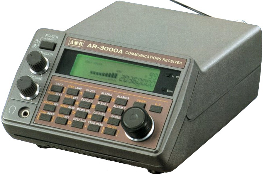
The AOR AR-3000A is a wideband communications receiver, made in Japan, covering 100KHz - 2.036 GHz with all popular modes including AM, NFM, WFM, CW, USB and LSB. the AR-3000A can be considered a tabletop unit, it is quite small, measuring only 8" x 5" x 3.5". The AR-3000A has a total of 400 memory channels, with four "Banks" (Banks A- D) each holding up to 100 channels. Each stored channel holds all the necessary parameters such as frequency, mode, attenuator, and step size. The first channel of each bank may also be used as a priority channel. Other features include: signal strength indicator, clock with sleep timer, tuning knob, keypad entry, record jack, attenuator and RS-232 port.
General information:
- Manufactured between 1991-99 by AOR
- 3 band analog PLL tuner HF, VHF and UHF receiver/scanner
- Coverage: 0.1 - 2036 MHz (cellular blocked)
- Tunning steps: any multiple of 50Hz up to 999.95kHz
- Antenna input impedance: 50 ohm BNC
- Memory: 400 regular in 4 banks, 100 lockout per bank, 4 priority, use one 203 lithium battery for backup
- Usable sensitivity: on AM 0.1 - 2.5 MHz 3.2uV, 2.5 - 1800 MHz 1uV, 1800 - 2000 MHz 3uV; on FM 2.5 - 1800 MHz 0.35uV, 1800 - 2000 MHz 1.25uV; on WFM 2.5 - 1800 MHz 1uV, 1800 - 2000 MHz 35uV; on SSB 0.1 - 2.5 MHz 1uV, 2.5 - 1800 MHz 0.25uV, 1800 - 2000 MHz 0.75uV
- Selectivity: AM/FM: 12kHz (-6dB), 15kHz (-70dB); WFM: 180kHz (-6dB), 800kHz (-50dB); SSB/CW: 2.4kHz (-6dB), 4.5kHz (-60dB)
- IF frequencies: 1st between 0.1-500MHz is 736.23MHz, 500-940MHz is 352.23MHz, 940-1300MHz is 198.63MHz, 1300-1650MHz is 352.23MHz and 1650-2036MHz is 736.23Mhz; 2nd 45.025MHz; 3rd 10.7MHz, and/or 455kHz
- AF output power/impedance: 1.2W/ 4 ohms or 0.7W/8 ohms at 10% distortion
- Audio signal output on AUX socket pin4 is 1.2V/1kohm, on pin5 5mV/220kohm
- Power: 12-14 Vdc, max. 300 mA. Is recommended power supply which can deliver more than 800mA
- Dimensions: 138x80x200 mm, weight 1.2 kg.
- Price at 1990: 1063 USD
Good things:
- Low noise level
- Small size
- Good sensitivity
- Several modifications can be found on the web about this receiver
Difficult, problematic items:
- The speaker is on bottom side, and has a small diameter - not the best audio quality
- A bit complicated menu
At the moment, I've only changed the electrolytics with high capacitance (100uF/6.3V, 220uF/16V, and 470uF/16V), which were all far from nominal capacitance, had high loss (between 6-18%), and had a high ESR (up to 8 ohms!).
Unfortunately, I bought this set without a power supply. In the beginning and during repairs, I used a PWM type. For final use, I created one specifically for this radio: from a 9Vac/850mA wall plug type, I inserted into it one rectifier bridge, 2x470uF/16V, 0.1uF/50V X5V, and one EMI filter transformer with 2x570uH. After the first trial, I didn't believe how clear the audio was!
Audion/Innerein/Rosita
Looks almost like a completely undocumented history, but based on my research, the equipment comes from Rosita Tonmöbel company, founded on November 9, 1954. Over years Rosita become a factory for "sound furniture" that just bought individual components from different manufacturers and built them into their unique design music cabinets. The electronics come from different famous companies of that era, like Grundig, Philips, Marantz, Dual, to name just a few of them, but cheap devices, like cassette recorders, come from the Far East (Korea). Seems Südfunk-Apparatebau was the assembly company of those devices into one system (like also for Neckermann). The company used different brand names to sell their assembled final products, which had the almost same internal or external design, style, and functions and appears under brand names like Audion, Rosita, Innerein, or Südfunk. On March 31, 1988, after 33 years, bankruptcy proceedings were opened.
Audion T6800
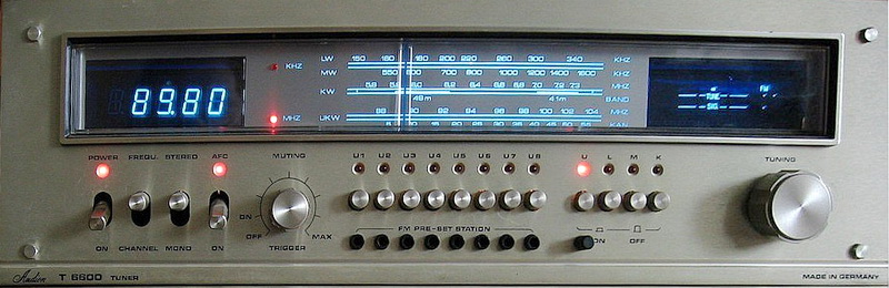
This tuner is almost a copy-paste of the Dual's CT1640, with no clock function, and instead of 2 analog instruments has a tube display for signal and tune. The main plate from Dual is replaced with several smaller boards: 2 for LEDs, one for tune/signal display unit, one for memory control and remote antenna system, one for "memory" settings, and the switchboards and commands as the main board. The audio output contains the improvements introduced by Dual on its CT1641 model. All components, PCBs, and their design style are the same as was used by DUAL in that era.
General information:
- Manufactured between 1977-78 by Rosita, but the electronics with high probability is from Dual Gebrüder Steidiner St. George/Schwarzwald
- 4 band analog PLL tuner LW, MW, SW, and FM
- Coverage: LW 150 - 340 kHz, MW 510 - 1620 kHz, SW1 5.75 - 7.4 MHz, and FM 87.5 - 104.0 MHz
- Tunning steps: fully analog, with additional digital display
- Antenna input impedance for FM: 60/75 ohms unbalanced and 240/300 ohms balanced
- 7 preset memories for FM, and no for AM (LW+MW+SW)
- Usable sensitivity: 20uV on MW, 30uV on LW, 10uV for SW, 0.7uV on FM (mono) and 2.5uV for stereo
- Intermediate frequencies: 460kHz for AM, and 10.7MHz for FM
- AM tuner IC: TDA1046; FM det. CA3089; stereo decoder (MPX) MC1310P; prescaller: 10131, 74LS90, 74LS93; radio receiver frequency counter & display driver AY-5-8100; voltage regulators uA78M05C and uA78M15C; LM3302 comparator, program setting ICs SN29770 and SN29771,
- Output frequency range:20Hz - 16kHz (for 50us pre-emphasis -3dB)
- Channel separation: 40dB at 1kHz
- Automatic mono/stereo switchover (FM): 6uV
- Muting level adjustment: 1.5 - 200uV
- FM IF bandwidth: 140kHz
- Signal to noise ratio: mono 66dB, stereo 62dB
- Harmonic distortion_ mono 0.15%, stereo 0.3%
- Stereo separation: higher than 40dB
- 19/38kHz suppression: better than 35/45 dB
- Power: ~110/220V, 50/60Hz internally selectable via fuse position, consumption 35W
- Output signal level and impedance: 750mV/5.1kohm
- Dimensions: 440x150x384mm, weight 9 kg.
Good things:
- Very clear and pleasant sound
- Audio buffer at the output is made from discrete components, and at the output has a 19KHz LC filter
- Adjustable muting not just on FM, also for AM
- In Germany the FM was divided in numbered channels. The tuner has a switch to change on the display the received frequency or the channel number (CH)
Difficult, problematic items:
- Has just DIN audio output, no RCA
- The signal level and also the tuning indicator has just 3, respectively 7 values, the analog instrument is more precise and continuous.
- Both PCBs with LEDs are just attached with double side tape to front panel, also the memory buttons, one by one.
- Very heavy and robust chassis, 9kg!
- No ferrite rod antenna, AM can listen just with an external antenna
- FM band is shorter, going from 87.5MHz till 104MHz
- Difficult to repair: the memory setting boars are screwed to the command unit with plastic spacers between panels on screws. The multiwire-cables are directly soldered on one side to PCB, LED's PCBs are glued to front-panel.
The whole electronics seems to be from Dual CT1640 or CT1641.
Problems: the main unit oscillator fine adjustment missing, is just simply mounted, not like in Dual CT1640.
All 0.1uF ceramic capacitors' capacitance was between 71-76nF, recommended to be changed (like in the case of Dual CT1640), were changed to SMD (3212 size, X5R, Samsung) type soldered on soldering side of PCBs. The service manual found on the net contains mistakes. The C309 value in the loop filter mounted is 220nF, not 22nF like in the schematic. The units connection in the schematic is a nightmare, is quite difficult to find some links where goes.
Modifications: C211 47nF, to IC201 (CA3089) pin 15 and 13 added 1nF to ground (recommended by datasheet), C303 470uF/25V + 22nF, C313, C314, CC1102, C1103, C1411, C1412 to 470nF, C416 47uF dry cap, C601 to 3300uF/25V, C603 to 4700uF/35V, C1111 and C1112 to 4.7uF pp, C1212 and C1244 to 100uF/16V dry caps, C1246 100uF/35V dry cap, C1402 to 4700/50V, C1405 1000uF/50V. Between pin 3 of IC301 (MC1310) and ground mounted 820pF (recommended by datasheet) to compensate the phase lead of 5.5 degrees.
Conclusion: this purple-blue design, used by Marantz, and inside with Dual CT1640 design make this tuner a very good one, underappreciated regarding its unknown brand name. On FM sounds better than the Dual AT1640, but on AM (MW and SW), is very poor, low sensibility - eventually if you have a good external antenna, can be also one of the best ones.
Blaupunkt
Founded in 1923 in Berlin as "Ideal", the company was acquired by Robert Bosch AG in 1933. In 1938 it changed its name to "Blaupunkt", German for "blue point" or "blue dot", after the blue dot painted onto its headphones that had passed quality control. After the World War II, Blaupunkt moved its headquarters and production to Hildesheim. Blaupunkt took over a former Philips/Grundig factory in Portugal to produce automotive head units. Later, factories were set up in Tunisia (speakers) and Malaysia (speakers and electronics). At 1 March 2009 was sold to Aurelius AG of Germany. After the 2011 take-over, Blaupunkt became a managed brand name with all production outsourced to China. It filed for bankruptcy in late 2015 with liquidation proceedings completed in early 2016. The brand is now managed by GIP Development SARL of Luxembourg and is used on various product groups worldwide. Unfortunately, I did not recommend any new equipment from this brand. They are characterized by low cost and low quality.
Blaupunkt RX+ 12
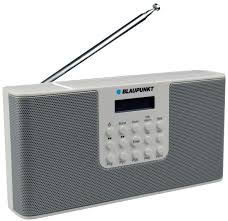
This was my first DAB+ radio, and frankly, I was disappointed by DAB+ reception quality, compared to FM transmission received with good tuners.
General information:
- Digital FM and DAB+ radio with alarm clock function
- Coverage: FM 87.5MHz - 108MHz (just one speaker, and no stereo in phones), DAB+ 170-240 MHz (band III, channels 5A-13F)
- 50 kHz steps on FM
- One chip radio, without any filters and resonant circuits
- Full RDS on FM and DAB+ bands
- 20 presets (10 for FM / 10 for DAB+) + timer memories
- Rec out jack (stereo, line level - I never try it)
- Frequency synthesizer DSP / microcontroller: Q88 BV158MOA or 57297AOD (I did not find any data about it on the net)
- Other ICs:F40-100GCP 4k serial static memory, LM4871 boomer 3W audio opamp, XC6206 3.3V LDO regulator
- Output: 1.2 W max. on 8 ohm
- Power consumption: 3 W via 4 AAA batteries or via 5V/500mA external power plug. In standby mode: < 1 W
- Dimensions/weight: 191 x 118 x 32 mm, 615 g (incl. batteries)
- Produced: since 2014 by M3 Electronic GmbH under Blaupunkt brand name
Good things:
- Quite sensible on both FM and DAB+ bands, no any more accurate specification (like service manual, info about sensibility, signal level, noise level etc.) about radio on user manual or on the net
- Clock adjustment is instant in DAB+ mode, but also are made on FM via RDS data, but more slowly.
- The Radio Text function is very good. You can select via Info/Alarm button
Problems:
- High consumption, with batteries the operation is meaningless, because in 2 days the cells are over. Stand by consumption is high (few mA-s) regarding continuous backlight of LCD.
- Sound quality is poor, regarding one small speaker with <5 cm diameter.
- Backlight LED is always on - has 2 light levels, a high one when the keypad are touched, and after 40 sec goes into low level, which is still high intensity in my opinion
- If the external power socket are taken out or in, the radio goes into standby mode, loosing all presets and time/alarm adjustments.
- Just 10+10 presets are not enough for today's radio listening in urban life.
Upgrades:
- Modification for AAA accumulator usage instead of batteries: one diode 1U4007 and one 100 ohm resistor added to power socket to have charging possibility using 4 pcs of NiMH AAA accumulators.
- The radio design from outside looks like to have 2 speakers (see the picture of radio above), but is not true. On the left side the radio has a 92 grams metal weight to balance the right side speaker weight (magnet). I added one more 8 ohm 1.5W speaker (same as original one) on left side instead of weight. Speakers are connected serially, now the load is 16 ohm. Sound level seems same (theoretically should be half), and sound quality seems to be a bit better, but do not expect significant improvement.
Verdict: not recommended. Regarding high consumption is not a portable radio, and the sound quality is poor (after modification is a bit better). Has just only one good point: sensibility on both bands, FM and DAB+, is good.
Dansk 3F / Tunsram
Hede Nielsens Fabrikker (A/S Hede Nielsen) was a big industrial firm in Horsens founded in 1906 by Niels Hede Nielsen that manufactured at beginning bicycles and parts. Around 1955, Hede Nielsen began manufacture of the newest high-tech product of the time: the television. The radios and televisions were sold under the Arena name, and in the 1960s, the factory was Denmark's largest. During the same year, bicycle production accounted for 25% of the Danish market. Hede Nielsen was the largest employer in Horsens at the time, with around 1800 employees countrywide. Ove Hede Nielsen's son, Leif Hede Nielsen (born 1940), worked as sales director at the Arena manufacturing.In 1966, Hede Nielsen established a new radio/TV facility on the outskirts of Horsens. After it burned down in 1970, it was reconstructed in conjunction with the English Rank organization. A new business called "Rank Arena" maintained production until 1975. The company was then taken over by the employee-owned 3F (Folke Fjernsyns Fabrikken = The People's Television Factory). Tungsram purchased shares for 1.5 million DKK in 1976, and the devices are now sold under the 3-F/Tungsram brand name. However, due to losses, production was halted in 1979, and the company declared bankruptcy. Tungsram had lost over four million DKK on 3F.
Dansk 3F T3535 / Tungsram T3535
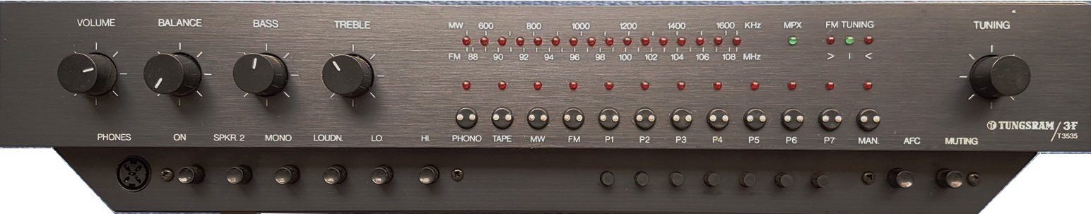
The T3535 was the final receiver produced (or perhaps just designed?) by 3F, formerly known as the Arena Danish factory. Concerning the ownership of Tungsram and the stock that has accumulated unsold, this was also sold in the Hungarian market during the years 1979-1980. The receiver features a distinctly modern or unconventional shape, showcasing a contemporary design with touch buttons and a radio scale showed by LEDs, along with an atypical adjustment for treble, bass, and loudness.
General information:
- Manufactured by 3F, Horsens, Denmark and/or Tungsram, Budapest, Hungary between 1978 - 1979
- Analog 2 bands (MW-FM) PLL radio,
- 7 memory presets, for both AM and FM bands
- Coverage: MW 520kHz - 1.650MHz, FM 87.5MHz - 108.0MHz
- Usable sensitivity: 400uV on AM, 1.5uV on FM (mono) and 5uV for stereo
- FM tuner IC: TCA420A, stereo decoder: MC3410P, AM tuner: TDA1046, power supply and AGC: TCA750, scale: UAA170, source and program selectors: SAS560S (2 pcs) and SAS570S
- Muting level: 5-10 uV
- Channel separation: 40dB
- Image rejection: 80dB on FM
- IF rejection: 80dB
- AM suppression: 50dB
- 19/38kHz suppression: 55dB
- Output frequency range: 18Hz - 15kHz (-1...+1dB) on FM, 20...5100Hz +-3dB on AM
- Signal/noise ratio: AM 50dB, FM 80dB
- THD: less than 0.3%
- Stereo separation: 45dB
- Line output level and impedance: 0.6V for FM, 0.2V for AM, 3 kohm
- Antenna input impedance for FM: 75 ohm, unbalanced
- Output power of amplifier: 2x41.6W/4 ohm or 2x32.4W/8 ohm
- THD at max power less than 0.15%
- Power bandwidth of amplifier: 20...30kHz, +-3dB
- Input levels: Phono 1.6mV/36kohm, Tape 60mV/100kohm
- Max. imput levels Phono 28mV, Tape 1V for THD max. 0.3%
- Bass adjustment: at 40Hz +13...-16dB
- Treble adjustment: at 12.5kHz +18...-20dB
- Loudness: at 40Hz +15dB, at 12.5kHz +6dB, at 14kHz +18dB
- Balalnce adjustment: -50dB
- Line/Tape output level: 56mV/50kohm at 1kHz
- Headphone max. output level on 100ohm: 11.8V
- Power: 220V/240 Vac, 50/60Hz, consumption: 165W
- Dimensions: 450x93x290mm, 6kg
- Original price at 1979: 16000 HUF = 450 US$
Good things:
- Warm sound
- Interesting front plate design
Difficult, problematic items:
- Difficult to repair. The circuit is on multiple PCBs, but the connections and mechanical fastening are not stable.
- The components, including heatsinks, capacitors rated voltage, are under designed.
- Low sensitivity on the AM band.
- There is no fuse on the priming side of the power transformer.
In Hungary, this receiver was sold by Ravill, Ramovill, Keravill, and Centrum supermarkets. Ramovill service company converted the FM tuner (made by Philips) from the CCIR standard and adjusted it to accommodate the enlarged frequency range from 65.86 MHz to 108.7 MHz, covering both, OIRT and CCIR FM standards but with lesser sensibility. This change was done superficially, primarily by removing some capacitors and replacing the varicaps diodes from BB110b to BB139.
Inside has a modular design, which was one of the Horsens engineers' main ideas: everything is on its own panel, with production capacity and debugging in mind. Symbiosis is home to 11 printed circuit boards, each with thread-thin color-coded solid wires zigzagging all over the place.
One half of the two secondary transformers supplies power to the output stage's power supply panels. Its buffer capacitors are buried beneath the rectifier panel, which also has the fuses on it, and, unlike the rest of the device, are artisanally soldered to a single driven wire rod. Interestingly, the power amplifier operates at a voltage of about +-34.7V and the buffers rated voltage is 35V, suggesting that the Danish engineers have 'tweaked' it. However, the 2×10000uF would be the envy of many more serious amplifiers. The output stage output is 2*35W at 4 ohms, as shown by the model number (T3535).
The manual station finder may be wrapped without end stops and includes a 2:1 gear ratio mechanism for finer adjustment. This is accomplished ingeniously with two clamped metal discs mounted on the tuning potentiometer's crankshaft, sandwiched between which is the shaft's metal jeweled plate on the other side of the winding knob.
Modifications:
In the tuner section, following C43 and C44, I introduced an FM IF amplifier made of one transistor (15pF+2SC1363+200k+2x2.2k+22nF) and wired it to C53. The FM section became more lively!
In the power supply, replace C39 470uF/40V with 2pcs 470uF/63V and C35 with 220uF/63V (for safety as the included capacitors were close to their maximum rated voltage). C10 on the AM panel was replaced by a 100uF/16V dry electrode instead of 47uF, and C24 (stereo decoder) was replaced by 470uF/25V (typically good for the stereo decoder's power supply). C17 on the filter panel was replaced with 1000uF instead of 470uF, while C7 on the volume panel was replaced with 330uF instead of 22uF. The TCA750's 5th pin received a 22uF capacitor based on the datasheet and is now fully stable (position exists on the PCB but was not installed). TR4, previously BC173, has been replaced by BC211, which is a 300mA type.
For C19, the polarity was reversed, but I fitted a 2.2uF foil capacitor, so the polarity is no longer important. It should be noted that the polarity of the C8 is drawn reverse on the display panel based to the service manual, despite the fact that it is correctly placed in the units - therefore be aware of this while working from the service manual. I used 22uF here.
To filter radio frequency sounds in the RIAA corrector, insert 220...470pF between the base and emitters of TR1 and TR2 (with some devices, an AM radio signal can be heard adjacent to the tracks on the LP).
Denon
Denon is a Japanese electronics company started in 1910 by Frederick Whitney Horn, an American entrepreneur. Denon produced the first cylinder audio media in Japan and players to play them. Decades later, Denon was involved in the early stages of development of digital audio technology, while specializing in the manufacture of high-fidelity professional and consumer audio equipment. Denon made Japan's first professional disc recorder and used it to record Emperor Hirohito's voice. For many decades, Denon was a brand name of Nippon-Columbia, including the Nippon Columbia record label. The Denon brand came from a merger of Denki Onkyo (not to be confused with the other Onkyo) and others in 1939. In 2001, Denon was spun off as a separate company with 98% held by Ripplewood Holdings and 2% by Hitachi. In 2002, Denon merged with Marantz to form D&M Holdings. On March 1, 2017, Sound United LLC completed the acquisition of D+M Holdings.
Denon TU-630
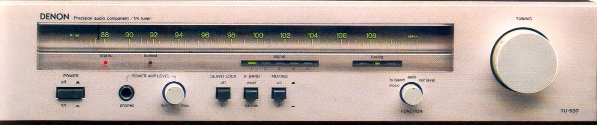
The TU-630 tuner with built-in monitor amplifier was introduced in 1978, a year after the well-respected TU-850 and a couple of years before the TU-900. It is an FM only with 5 gangs and 5 ceramic filters, dual IF unit using what, at the time was near top of the line components. The front panel has the usual buttons for IF band, Power, Muting and Servo Lock, and has a headphone jack for listening with own amplifier and speaker connectors on back side to be listened loudly (2x3W). The Function rotary knob has detents for Mono/Hi Blend/Auto and Recording Level. The Back panel houses both 75 Ohm F and 300 Ohm twin lead antenna connections along with the speaker connections, fixed output audio, and H/V scope RCAs.
General information:
- Manufactured by Denon/Nippon Columbia, Tokyo, Japan 1978 - 1980
- Analog FM band PLL radio,
- No memory presets,
- Coverage: 87.5MHz - 108.0MHz
- Usable sensitivity: 0.85uV on FM (mono) and 13uV for stereo
- FM tuner IC: HA11225, IF amplifier TA7060AP, stereo decoder: HA11223, output amplifiers (2 pcs): TA7202P, signal level and tunning indicators (2 pcs): LB1415
- Antenna input impedance for FM: 75 ohm, unbalanced; 300 ohm balanced
- Muting level: 22dB
- Image rejection: 110dB
- IF rejection: 105dB
- Spurious rejection: 110dB
- AM suppression: 60dB
- Effective selectivity: wide 35dB (+-300kHz), narrow 80dB (+-400kHz)
- Capture ratio: wide 1.0dB, narrow 1.5dB
- Output frequency range: 20Hz - 15kHz (+0.2...-1.5dB)
- Signal/noise ratio: FM 82dB mono, 79dB stereo (for EU version)
- THD: for wide 0.03% for mono and 0.06% for stereo; for narrow 0.1% for mono and 0.12% for stereo
- Stereo separation: 55dB in wide, 50dB in narrow mode - both measured at 1kHz
- Muting action level: 20dB at 1.7uV on 300 ohm input
- Multipath output: vertical 50mV/10kohm; horizontal 350mV/10kohm
- Audio/line output level and impedance: 1.0V/3.3kohm
- Recording level check signal: 440Hz sine wave, 0.5V level
- Monitor amplifier rated output power: 2x3W at 1kHz on 8ohm load, S/N 105dB, THD less than 0.05%
- Monitor amplifier output impedance: 20Hz...15kHz +0.1...-1.5dB at 1W output is less than 0.5 ohm
- Monitor amplifier output at terminals: 8-16 ohm
- Power: 200V, 50/60Hz, consumption: 45W
- Dimensions: 434x99x364 mm
- Weight: 7.8kg
- Original price at 1979: 450DM
Good things:
- High sensitivity, high S/N ratio, and excellent interference rejection capability
- Very musical sound!
- Separate audio output buffers for each channel made with transistors
Difficult, problematic items:
- Designed with built-in servo-lock circuit, it performs effectively only if triggered following tuning. Give a very solid and precise station listening in this scenario.
- Exact tunning indication use just 3 LEDs
- My set is from Germany and contains a power transformer built for 200Vac, not 220Vac or 240Vac! This means that if the tuner is powered by 230V, each voltage on the secondary side is 15% higher, causing additional heat to be generated by the voltage regulator circuitry.
Five gangs and three N-MOSFETs are used in the front-end: two for amplification (2SK45 and 2SK59) and one for mixing (2SK59). The 2SC710 transistor is used to create the FM oscillator. Five ceramic filters are used in the IF parts: there are three Murata MM filters in the narrow IF and two Murata ML filters in the wide IF. With distinct separation adjustments for Wide and Narrow IFs, a passive de-emphasis is applied (not switchable; capacitors C49 and C50 with corresponding values are placed based on sales region). The power supply is complicated, with three distinct secondary windings for -9.7V (output muting), 22.9V for the monitor amplifiers, 23.5V for audio output buffers and the power audio output speaker protection relay. From this last one are generated 12.1V for the servo, wide/narrow circuit, IF circuits, frons-end, signal and tuning indicator circuits, and record level signal generator, and 13.6V for the stereo decoder alone. The tuning indication only uses three (left, center, and right) LEDs, but the signal level indicator uses five.
To reach the solder side of the PCB at first unscrew the PCB and front panel from the chassis, unhook all cable connectors, and then pull up the entire assembly.
Regarding it sound: this tuner sound very good with a nice soundstage. Separation is notably very good!
Modifications:
Power circuit: received an EMI filter (2x560pF/1kV+2x10nF/1kV+0.47uF/275Vac+2x11mH) between power switch and transformer. C90 and C95 were replaced with 2200uF/35V Nichicon, C36 with 470uF/35V Rubycon, and C21 with 47uF/50V Yageo capacitors.
Audio output buffer: R131 changed to 2x160ohm - powering the 2 output stages separately. C64 was doubled accordingly, it valuea are 220uF/35V/channel.
Generally speaking, the electrolytics next to the heatsinks (power regulator and power amplifiers, if utilized) are dead and need to be replaced.
Denon TU-747
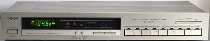
The TU-747 is a basic, inexpensive digital tuner, and has a good reputation compared with TU-767, but has a lack of muting circuit compared with it. In general, "looks good, sounds great, and for DXing is on a par with mid-line Kenwoods like the KT-7300 and KT-6500 when modified" - based on FM Tuner Info. Has 4 gangs on FM and 3 ceramic filters
General information:
- Manufactured by Denon/Nippon Columbia, Tokyo, Japan 1985 - 1987
- Digital 2 bands (MW-FM) PLL radio (has also 3 band version, with LW named TU-747L),
- 2x8 memory presets, 8 for AM and 8 for FM
- Coverage: MW 520kHz - 1.710MHz, FM 87.5MHz - 108.0MHz
- Tuning increments: 0.1MHz on FM, and 9/10 kHz on AM
- Usable sensitivity: 18uV on AM, 0.8uV on FM (mono) and 23uV for stereo
- FM tuner IC: HA11225, stereo decoder: HA12016, AM tuner: LA1245, FM IF amplifier TA7060AP, prescaller: TD6104P, uController: TC9147P, display driver TD6301AP, signal indicator: LB1426, OP: NJM4558D
- Muting level: 22dB
- Image rejection: 80dB on FM, 45dB on AM
- IF rejection: 85dB
- AM suppression: 60dB
- Output frequency range: 20Hz - 15kHz (-1.5...+0.2dB)
- Signal/noise ratio: AM 50dB, FM 82dB mono, 78dB stereo (for EU version)
- THD: on FM 0.1% for mono, 0.3% for stereo; 0.6% for AM
- Stereo separation: 45dB
- Line output level and impedance: 0.6V for FM, 0.2V for AM, 3 kohm
- Antenna input impedance for FM: 75 ohm, unbalanced
- Power: 230V/50Hz, consumption: 8W
- Dimensions: 434x66x281mm, 3.3kg
- Original price at 1986: 250$
Good things:
- Clear sound, good readable display
- Very simple and elegant front design
Difficult, problematic items:
- Auto/mute or mono switch, which means in stereo mode the mute is activated. Below muting level, the stereo program cannot listen in stereo
- Has just only 220V/50Hz input, but nowadays in EU we have 230V/50Hz+deviatio -> in my home the supply voltage is higher by 10% than the rated voltage of the tuner.
- Low sensibility and sensitivity on AM band
- The AM output is just the 3rd of FM output level - which means when you switch from FM to AM, you should increase the volume on the amplifier. When you switch back to FM and forget to decrease the volume, you will have a heart attack regarding instant high sound level
This tuner appears 2 years after TU-767, an older and midrange brother - can be mentioned is a low-cost version of TU-767. Compared with TU-767 has one common buffer to drive varicaps for AM and FM, no output buffer, no narrow/wide IF filtering for FM, and the signal level indicator shows just 3 levels, not 7, a simpler power supply circuit. The display driver and memory selection PCBs are the same
Modifications:
To improve the AM output level, R512 was changed from 27K to 3.3k, and C513 (based on the schematic should be 68nF) from 22nF was changed to 0.1uF foil capacitor. To improve the noise suppression between stages, the power line of HA11225 received a 3.3uH inductor (pin 11) in jumper position J37, and the digital stage also a 100uH inductor instead of jumper J26 (this is the supply line for prescaller and microcontroller). Deviations from the service manual: C513 value was just 22nF instead of 68nF, C611 value was 100uF/10V instead 470uF/6.3V. Between pins 4 and 11 of IC2/HA11225 are mounted one 22nF ceramic capacitor, at tuner section between AGC and Vt inputs are mounted one 1Mohm resistor, and between AGC and Gnd another of 910kohm - all not existing on the schematics.
Changes in power line C203 changed to 1500uF/25V, C529 changed to 270uF/16V, C607 changed to 100uF/16V, C611 changed to 470/6.3V, C804 220uF/25V, C805 and C807 to 270uF/16V. Change in AM signal output: R512 to 3.3kohm, C513 0.1uF. Tuning buffer: C603 to 1uF/63V foil. AM section: C521, C522, and C523 22nF. FM section: C7 and C8 47nF, C14 1uF/63V. Audio signal: C101, C102, C201, C211 and C212 4.7uF/50V foil capacitor (Wima).
Denon TU1500RD
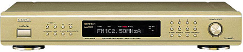
Is one of my best tuner, used especially for FM classical music programs in my audio system. Has a very good sensitivity and selectivity on FM, I can receive some stations, which I can't receive with any other tuners owned by me (excepting some Duals, Kenwoods, and Marantz tuners). Is possible to use RDS for "smart searching", for instance, you can select as an example to search only classical music or news stations, etc.
General information:
- Manufactured by Denon in Japan between 1999 - 2006
- Digital 2 bands (MW-FM) PLL radio with RDS+EON capability,
- 40 memory presets
- Coverage: MW 520kHz - 1.710MHz, FM 87.5MHz - 108.0MHz
- Usable sensitivity: 12uV on AM, 0.9uV on FM (mono) and 16uV for stereo - via a very sensitive MOSFET FM tuner
- FM/AM tuner IC: FM/AM tuner: LA1265, stereo decoder: LA3401, PLL freq. synthetizer: LC72131, uController: TMP87CM71F, dot matrix VFD display driver LC75711, RDS decoder: SAA6579T & LC7074
- Output frequency range: 20Hz - 15kHz (-1...+0.5dB)
- Signal/noise ratio: AM 53dB, FM 82dB mono, 78dB stereo
- THD: on FM 0.08% for mono, 0.12% for stereo
- Stereo separation: 50dB
- Line output impedance: 100 ohm
- Antenna input impedance for FM: 75 ohm
- Power: 230V/50Hz, consumption: 9W
- Dimensions: 434x75x242mm, 2.5kg
- Original price at 1999: 600$
Good things:
- Has a very clean sound, beautiful bass, low noise, good channel separation (as radio, cannot be compared with CD, SACD or DVD-A), good readable dot matrix display, perfect "narrow" IF selection feature.
- RF-attenuation for strong stations.
- Remote has digit button to direct access the memory and keys for RDS (I just try it, but I did not use the remote).
- Has Radio Text
- Has a Postdetection Filter to eliminate HD FM radio noise (used in America)
Difficult, problematic items:
- Has no signal level indicator (could make antenna placement more easier)
- Memory is organized like 5 x 8 = 40 positions (A:1-8, B:1-8, ... ,E:1-8). Should be more natural 4x10 = 40
- Has just only 1 antenna input. Some tuners have 2, and for DXing could be more suitable.
DX-ing:
On dedicated webpages are recommended to modify the IF filter for FM from 230kHz bandwidth with a 150 or 110kHz type. Nowadays, ex. Murata or TDK has low loss type narrow band (150 or 130 kHz) ceramic filters. What is the advantage to change the filters with a narrow band low loss type one? Muting the adjacent channels without sensibility decrease! I changed the narrow filter part (CF102 and CF103 position) with low loss, narrow band TDK filters: 107MJ 150kHz+-20kHz, 4.5dB loss type. Original filters were Murata type, in CF101 positions SFE10.7MXHA (low distortion, 230kHz+-25kHz), 2 pcs of SFE10.7MS3GKA (180kHz+-20kHz) at CF102 and CF103 position, and SFE10.7MM (230kHz, +-25kHz) in position CF104.
Related links:
Audioreview, is a review site with several reviews about this tuner. Do not be surprised when you saw just 4/5 score, because some reviews referring to TU-1500AE, and are written by novice members, not technical gurus. Almost all of them write about exceptional selectivity and sensibility of this radio, mentioning no signal indicator and 5x8 memory location, and high price (at that time).
Tuner Information Center - Vintage stereo tuners - tuners review from D to G. Is a good review of TU-1500RD tuner
The FM Ceramic Filter Page mentioning, in general, the Denon TU-1500RD "is the best tuner for high-quality FM DX audio program listening".
Denon TU1500AE
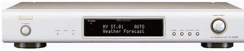
Is an upgraded version of TU-1500RD - based on Denon. Personally, I have a different opinion. From design and used semiconductors can be mentioned that, but for DX-ing cannot be used (see later the explanation).
General information:
- Manufactured by Denon in Japan between 2005 - 2010
- Digital 2 bands (MW-FM) PLL radio with RDS+PTY+TP and Radio Text capability,
- 100 memory presets
- Coverage: MW 522kHz - 1.611MHz, FM 87.5MHz - 108.0MHz
- Usable sensitivity: 18uV on AM, 1.0uV on FM (mono) and 23uV for stereo - via a very sensitive MOSFET FM tuner
- FM/AM tuner with IF section: one module, uController: MB90C950, RDS decoder: BU1924, and opamp: SE5532
- Output frequency range: 20Hz - 15kHz (-1...+0.5dB)
- Signal/noise ratio: AM 50dB, FM 73dB mono, 68dB stereo
- THD: on FM 0.15% for mono, 0.3% for stereo
- Stereo separation: 43dB
- Line output impedance: 300 ohm
- Antenna input impedance for FM: 75 ohm
- Power: 230V/50Hz, consumption: 10W, less than 1W in standby
- Dimensions: 434x73x286mm (WxHxD), 3.6kg
Good things:
- Has a good readable dot matrix display, good channel separation, low noise, clean sound, but not as pleasant or as musical as its predecessor, TU-1500RD.
- RF-attenuation for strong stations.
Difficult, problematic items:
- Has no signal level indicator (could make antenna placement more easier)
- No any selection possibility of wide or narrow IF bandwidth
- No direct memory recall buttons, all can be selected via rotating knob.
- Cannot be switched off the stereo mode (at weak signals should be better if you can switch into mono mode) or to listen something in mono.
- This tuner is not good for DX-ing. Is quite difficult to often change between tunning modes (manual and automatic searching modes) in case of weak signals.
- The tuner and IF part are placed into a metal box inside, highly populated with components, which makes it difficult to change the ceramic filters and electrolytic capacitors in IF part.
- In flyer are mentioned the output impedance is less than 300 ohm, but the output coupling capacitors value is just 10uF, which means the lower output frequency should be around 55-60Hz
- In several reviews are highlighted the clear sound of this tuner, but in reality, the electrolyte capacitors' quality is poor. Is better to change them with higher quality and values (ex. 47uF/25V Nichicon Fine Gold).
- Not necessary, but improving the sound quality: changing the opamp power capacitors from 100uF/16V with 220V/16V, and using Ta capacitors around microcontroller and RDS decoder instead of electrolytic for the noise canceling, and insert the power line noise filter components on PCB, etc.
- I did not found the Service Manual of this radio, but I recognized, the PCB is same with TU-1800DAB model, so also the related part of the schematic. Can be very helpful!
I recommend it just for daily listening, in urban area, with a lot of stations around. Is a very good tuner, but just within mentioned conditions.
Dual
In 1907, brothers Christian and Joseph Steidinger began manufacturing clockwork and gramophone parts in the Black Forest town of St. Georgen. In 1927, Gebrüder Steidinger (Steidinger Bros.) adopted the name Dual in reference to the dual-mode power supplies it pioneered. The power supplies allowed gramophones to be powered from mains electricity or with a wind-up mechanism. Soon thereafter, Dual began producing turntables of its own. After World War II, Dual became the biggest manufacturer of turntables in Europe, with more than 3,000 employees working in several factories. Throughout the 1970s, 1980s, and 1990s, Dual introduced audio cassette players, VCRs, CD players, and other consumer electronics. When Japanese consumer electronics started entering European markets in the 1970s on a large scale, Dual went bankrupt in 1982, and was sold to French electronic manufacturer Thomson SA. In 1988, Thomson sold Dual to German manufacturer Schneider Rundfunkwerke AG. After the insolvency of Schneider Rundfunkwerke AG in 2001, TCL Holdings, a Chinese company, purchased the Dual assets and brand, and it began marketing its own products under the name. In 2002, Namsung Electronics, a Korean company, bought the rights to use the name in the Americas and began selling lower-priced (but generally well-reviewed) consumer electronics under the Dual marque. The main product lines are home audio, mobile audio, marine audio and GPS receivers.
Dual CT-1640
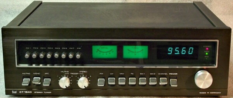
General information:
- Manufactured between 1977-78 by Dual Gebrüder Steidiner St. George/Schwarzwald
- 5 band analog PLL tuner LW, MW, and FM
- Coverage: LW 150 - 340 kHz, MW 500 - 1640 kHz, SW1 5.7 - 9.1 MHz, SW2 9 - 16 MHz, FM 87.5 - 104.0 MHz
- Tunning steps: LW and MW 1kHz, SW 5kHz, FM 50kHz
- Antenna input impedance for FM: 60/75 ohms unbalanced and 240/300 ohms balanced
- 8 preset memory for FM, and no for AM (LW+MW+SW1+SW2)
- Usable sensitivity: 20uV on MW, 30uV on LW, 10uV for SW, 0.8 uV on FM (mono) and 20 uV for stereo
- Intermediate frequencies: 460kHz for AM, and 10.7MHz for FM
- AM tuner IC: TCA440; FM det. CA3089; stereo decoder (MPX) MC1310P; prescaller: 10131, 74LS90, 74LS93; radio receiver frequency counter & display driver AY-5-8100; 4 digit clock AY-5-1202; voltage regulators uA78M05C and uA78M15C; LM3302 comparator
- Output frequency range:20Hz - 15kHz (for 50us pre-emphasis -3dB)
- Channel separation: 40dB at 1kHz
- Automatic mono/stereo switchover (FM): 4uV
- FM IF bandwidth: 140kHz
- Signal to noise ratio: mono 68dB, stereo 63dB
- Harmonic distortion_ mono 0.15%, stereo 0.3%
- Stereo separation: higher than 38dB
- 19/38kHz suppression: better than 35/45 dB
- Power: ~110/220V, 50/60Hz internally selectable via fuse position, consumption 15W
- Output signal level and impedance: 750mV/5.1kohm
- Dimensions: 440x150x384mm, weight 9 kg.
- Price at 1977: 1080 DM
Good things:
- Very clear sound and stereo picture.
- Easy to repair regarding its modular structure
- Adjustable muting not just on FM, also for AM
- Switch to select the ferrite rod and aerial antenna (FA)
- Very heavy and robust chassis, 9kg!
- In Germany the FM was divided in numbered channels. The tuner has a switch to change on the display the received frequency and channel number (CH)
Difficult, problematic items:
- Has just DIN audio output, no RCA (for example Telefunken RT300 has both)
- The clock has no memory or battery. After each power line break must be readjusted.
- FM band is shorter, going from 87.5MHz till 104MHz, but can be modified
In the case of the analog part, also all electrolytes should be changed. The most common capacitor is the 2.2uF, I replaced them with Wima 2.2uF foil type (C117, C207, C210, C303, C409, C734, C737). In power part 2200uF/40V was replaced with 3300uF/35V (C601, C603, and C702), C705 was replaced with 1000uF/35V.
All 0.1uF ceramic disk capacitors (C101, C306, C307, C317, C318, C403, C405, C407, C408, C411, C602, C604, C703, C723, C733, C735, C1102, C1103, C1104) were replaced with 0.1uF/63V PP foil type. Reason: their capacitance decreased by 30% and loss increased to 0.3%. This change has also a good effect on sound because this type of capacitor is used also on the signal path in the FM IF module at the input of audio buffer.
Modification in stereo decoder: received a puffer capacitor on the power line (100uF/25V Oscon), C305 was changed to completely same value PP foil type - has better temperature stability than the ceramic disk capacitor. R313 and R314 at audio output changed to 5.6kohms, and the opposite side connected to pin 11 of decoder IC via two 100kohms resistors (an idea used in CT1641 model). The audio buffer output coupling capacitors (C1111 and C1112) changed to 10uF/50V bipolar Nichicon Fine Gold. C1101 was replaced with 100uF/35V Oscon.
Originally the FM bandwidth was 87.5 - 104 MHZ, but easily can be modified to listen to stations till 108.0MHz: replace the R121 with 1kohms, move the scale to the bottom of the band and adjust L102 till you can read on display 87.5MHz, and move the scale to the top of the band, and adjust R103 till you read 108.05MHz on the display. Select a program near to 89MHz and adjust the L101, L104, and L105 for maximum signal and low distortion. After looking for a program around 106MHz, and set for maximum signal and low distortion with R109, R113, and R120. You can repeat the last 2 steps for fine adjusting. If you cannot set the L101 or R109 because the coil comes out from the body or with R109 you reach the end, change the C103 from 20pF to 15pF C0G/NP0. That is all.
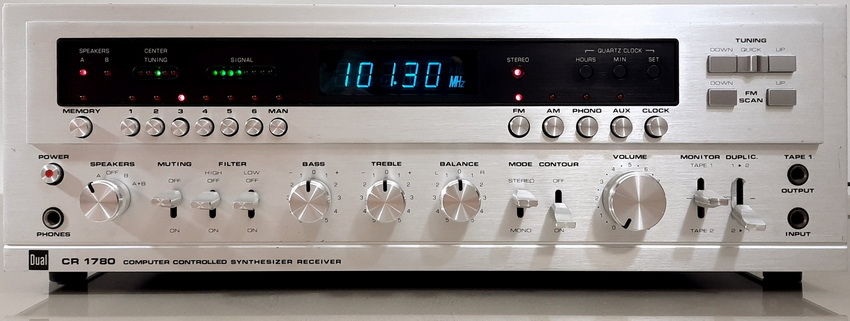
Dual CR-1780
General information:
- Manufactured between 1979-81 by Dual Gebrüder Steidiner St. George/Schwarzwald, but on some webpages is mentioned was made by Rotel in Japan for Dual (this is plausible because the whole internal circuitry is Japan made)
- 2 band analog PLL tuner MW, and FM
- Coverage: MW 513 - 1602 kHz, FM 87.5 - 104.0 MHz
- Tunning steps: MW 1kHz, FM 50kHz
- Antenna input impedance for FM: 60/75 ohms unbalanced and 240/300 ohms balanced (via DIN and screw connection). For AM: ferrite rod or external (high impedance)
- 6 preset memory for FM and AM
- Usable sensitivity: 15uV on MW, 0.6 uV on FM (mono) and 1,8 uV for stereo
- Automatic mono/stereo switchover: 5uV
- Muting control: insertion point 4uV, can be switched off
- Intermediate frequencies: 460kHz for AM, and 10.7MHz for FM
- Used integrated circuits: AM tuner IC: HA1197; IF amplifier HA1211, FM det. HA12412; stereo decoder (MPX) HA1196; prescaller TD6101P, freq. counter e1133, clock display driver MP1096, timebase TC5048 and 14040, other ICs 3x 14081, tunning indicator SI901P, signal strengths indicator 2x LB1405, opa for inputs and correctors 4x C4558C, RIAA 2x HA1457, protection circuit HA12002.
- Output frequency range:20Hz - 15kHz (for 50us pre-emphasis -3dB)
- Channel separation: 40dB at 1kHz
- Automatic mono/stereo switchover (FM): 4uV
- FM IF bandwidth: 140kHz
- Signal to noise ratio: mono 63dB, stereo 63dB related to 1kHz/40kHz deviation, weighted
- Pilot-tone attenuation: 65dB (measured via low pass filter)
- Harmonic distortion: mono 0.3%, stereo 0.3% - both measured at 1kHz/40kHz deviation
- Stereo separation: higher than 40dB at 1kHz
- Selectivity: 85dB
- Image rejection: 75dB
- Spurious signal rejection: 100dB
- Output power (measured on 8 ohms): 2x80W continuous, 2x120W music
- Harmonic distortion (at 2x80W/1kHz): 0.04%
- Power bandwidth (as per DIN45500): 10Hz - 60kHz
- Frequency response: 10Hz - 40kHz +-1.5dB
- Inputs: Tape1, Tape2, AUX and Monitor 150mV/470kohms, Phono MM 1.5mV/47kohms
- Maximum input levels: for high imp. inputs 11V, for Phono MM 120mV
- Tone controls: Bass at 50Hz +-15dB, Treble at 15kHz +-15dB
- Balance control: range over 55dB
- Rumble filter: limit frequency 70Hz (-3dB) 12dB/octave
- Noise filter: limit frequency 8.5kHz (-3dB) 12dB/octave
- Outputs: 2 pressure terminal strips for 2 speaker pairs switchable, 1 stereo headphone jack 6.3mm, 2 tape outputs RCA, 1 tape output DIN, 1 tape output stereo jack 3.5mm with switch contract
- Output voltage: for tape recording RCA 320mV, and 10mV for DIN jacks
- S/N ratio: for Tape1, Tape2, Aux and Monitor higher than 80dB, for Phono MM higher than 62dB
- Channel separation (at 1kHz): between inputs higher than 66dB, between channels higher than 57dB
- Power: ~115/230V, 50/60Hz internally selectable via fuse position, consumption 450W
- Dimensions: 440x150x405mm, weight 14 kg.
- Price at 1979: 1398 DM
Good things:
- Clear sound and nice stereo picture, similar to Japanese sets (because is an OEM Rotel).
- Shielded structure: top side the radio, display, and power amplifier, on the bottom side the RIAA, power supply regulator, and tone control circuits.
- Fast station searching circuit
- DIN and RCA tape and phono jacks
- Very heavy and robust chassis, 14kg!
- All parts has their own power regulator circuit, decreasing in this way the noise gerentated by different circuits
Difficult, problematic items:
- The FM band goes up just till 104MHz, and regarding the synthetizer circuit, cannot be modified to receive the stations between 104-108MHz. Because the extended FM band were implemented from beginning if 1980, and already other manufacturer start to sell receivers in 1979 with extended band, for me today is ununderstandable, why Dual/Rotel did not implement this extended band on this receiver. This deficiency can be eliminated using an extranal downconverter, to transfer this 4MHz bandwidth (104-108MHz) to some low density area within 87.5-104MHz, but that depends by your geographical location. In my case, thin means a shifting with 4.8MHz.
- The clock and the programmed stations have no back-up circuitry/ battery. After each power line break or disconnecting the set from power line, should be readjusted the clock and the presets again the station memories.
Unfortunately, the digital section's soldering process or that PCB's soldering joints treatment was incorrect. Several claims regarding this issue can be found on the net. The problem: looks like the solder did not adhere to the soldering pad. In several points, if you remove it (ex. during components change), can be seen the whole pad was oxidized, just on the perimeter has contact with the solder. This means if the components receive a minor force from the top, the soldering joint will be cracked. Is better, if you resolder all joints very carefully. During resoldering, you must check mechanically and via lupe the correctness of the joint.
The main integrated circuits used in digital and display parts are very specific, and I did not find any datasheet about them (e1133, MP1096, SI901P). If you have any datasheets about them, I will be delighted if you can send me (my email address is at the bottom of this page).
On my set, I found several problems: the before-mentioned digital parts soldering, the programming of stations does not work, and the sound was without clear bass (seems buffing) and treble seems "washed" and weak. Immediately I start to change all capacitors from the power lines of each circuit - and they mostly solved this issue. The most problematic capacitors: C434 instead of 1000uF, I measured 648uF with 4.3% loss and almost 2 ohms ESR. In the digital part's power supply the C445 was completely dead (instead of 220uF I measured 1.2uF, 8.3ohms ESR, and 5% loss) - this was responsible for the programming failure. In general other capacitors still have their nominal values, but their loss was all over 2%, and ESR were higher than 0.1 ohms.
The downloadable schematic has several errors, not just as component values (ex. C443 are mentioned as 10nF, but is 100uF, or C902 and C904 is 1500uF instead of 15000uF, etc.), but also as a circuit (power supply of the protection circuit, muting, and radio, but also in the digital part).
Modifications (not the changed components list!):
In power line: C416, C423 470uF/63V, C430 330uF/50V, C445 270uF/16V, C466 47uF/35V.
In audio: all C4558C opa was changed to NE5532. In the correction network of the RIAA both capacitors (6.8nF and 1930pF) were changed with mica capacitors. For me was a surprise one capacitor's value: 1930pF (C405) with 10% tolerance. Such value should fit in the 0.5% or 1% range, not in 10%. All 4 original capacitors were 10% type, related resistors in 5%, but their measured values fits in 3% tolerance range - probably were presorted. The RIAA circuit used isthe same as in the datasheet of HA1457.
In the radio part: C509 and C556 now are 270uF, C549 is 1500uF.
Chassis: the station searching push buttons (in total 5 pcs) were wobbly, no counterforce from the back (I don't know this was their original status, or somebody try to fix it and left out some springs). I inserted a rubber-sponge of 3mm between the buttons and the switches from the PCB. Now works fine.
Conclusion: is a fine tuner (especially after refurbishing), very sensible (0.6uV of FM!), warm sound (after changing the opa-s to NE5532 have good bass, and clear treble), and with a high power (90W on 8 ohm/channel!). With silver front looks very brave.
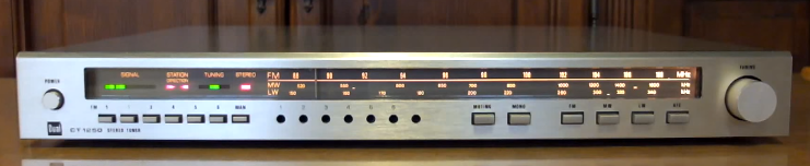
Dual CT-1250
General information:
- Manufactured at 1980-81 by Dual Gebrüder Steidiner St. George/Schwarzwald
- 3 band analog PLL tuner LW, MW, and FM
- Coverage: LW 150 - 340 kHz, MW 515 - 1620 kHz, FM 87.5 - 108.0 MHz
- Antenna input impedance for FM: 60/75 ohm unbalanced,
- 6 preset memory for FM
- Usable sensitivity: 15uV on MW, 30uV on LW, 0.8 uV on FM (mono) and 25 uV for stereo
- Intermediate frequencies: 460kHz for AM, and 10.7MHz for FM
- AM tuner IC: TDA1072 amp, osc, IF and det; FM det. TDA1576A; stereo decoder (MPX) TDA1578; tunning indicator TBB4331A
- Output frequency range:40Hz - 12.5kHz (-0.5...+0.5dB)
- Power: ~220V/50Hz, consumption 15W
- Output level and impedance: 750mV/4.7kohm
- Dimensions: 430x55x380mm, 3.4 kg.
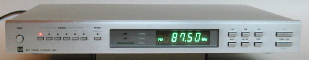
Dual CT-1450
General information:
- Manufactured between 1981-82 by Dual Gebrüder Steidiner St. George/Schwarzwald
- 3 band analog PLL tuner LW, MW, and FM
- Coverage: LW 146 - 353 kHz, MW 522 - 1611 kHz, FM 87.5 - 108.0 MHz
- Antenna input impedance for FM: 75/300 ohms unbalanced,
- 6 preset memory for FM, and 6 for AM (LW+MW)
- Usable sensitivity: 15uV on MW, 25uV on LW, 0.6 uV on FM (mono) and 20 uV for stereo
- Intermediate frequencies: 455kHz for AM, and 10.7MHz for FM
- AM tuner IC: HA1197; FM IF opamp: LA1222; FM det. uPC1167C2; stereo decoder (MPX) uPC1161; tunning indicator: LB1416; prescaller: uPB553AC; PLL freq. synthesizer and controller: uPD1703-016
- Output frequency range:10Hz - 16kHz (for 50us pre-emphasis -3dB)
- Automatic mono/stereo switchover (FM): 4uV
- FM IF bandwidth: 140kHz
- Signal to noise ratio: mono 76dB, stereo 74dB
- Harmonic distortion_ mono 0.15%, stereo 0.2%
- Power: ~115/230V, 50/60Hz, consumption 13W
- Output level and impedance: 750mV/5.1kohm
- Dimensions: 440x55x350mm, 3.4 kg.
Problem: the LW starts from 146kHz and the steps are 9kHz -> means cannot be received any LW station, because the normal LW station frequencies start from 153 + Nx9 kHz, and this radio is shifted with 2kHz, and originally are made in this way. In all specifications and catalogs are written for this radio LW band 146-353 kHz. I did not know why at tuners made before 1985 the LW band is shifted (Akai, Rotel, ...).
Accumulator was out of order (3.6V 30mAh NiCd type, made by Yuasa, Japan) - was necessary to be replaced. To be remarked: after more, than 40 years operation no any surge or oxidation mark on it! Same as all 470uF/6.3V capacitors in control board (measured capacitance was 291uF!). Basically, all electrolytics were changed.
In general, the Dual use low coupling capacitors values in its equipment between audio stages, is better to be changed into higher values.
EduTec
Edutech is a brand name owned by Eduscho, nowadays Tchibo for its home electronics. Same radio appeared under different brands names like Inconnu, Dak, Lifetec, Magnum (owned by Aldi), Ohayo, Universum (owned by Quelle), Starto, Watson and Westfalia Wetekom. The makes in a China, HngKong or Singapore - is not known
EduTec LT9095
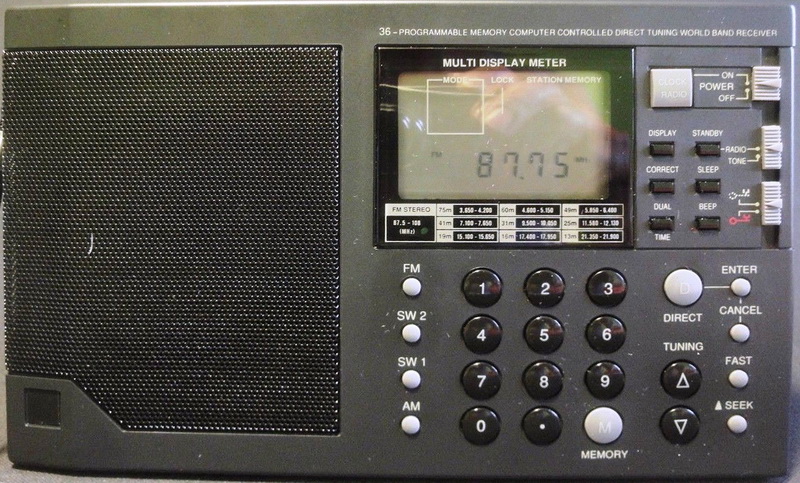
This is a 4-band computer-controlled world receiver featuring 36 programmable memories, along with direct, forward/backward, and automatic search tuning options. Features a Local/DX switch, headphone stereo output (32 ohms), standby mode, and a clock function. This model is available under various brand names: Dak DMR 3000, Fuze FS-3000, Inconnu R3000, Lifetec LT9095, Magnum WR-218, Ohayo PR-218, Strato WR-499, Universum (Quelle) TR1040, Watson (Aldi) TR 4061, and Westfalia Wtekom PLL 500.
General information:
- Manufactured in 1995 by an unidentified manufacturer, originates from the Far East.
- 3-band analog superheterodyne design with a digital PLL receiver, covering MW, SW, and FM bands.
- Coverage: MW 522kHz - 1.6020MHz, SW1 3.650kHz - 7650kHz, SW2 9500kHz - 21900kHz, and FM 87.5MHz - 108.0MHz
- Tuning steps: 9kHz on AM, 1kHz on SW and 10kHz og FM
- Station memories: 9 memory locations for each band, totaling 4x9 - 36 random preset memories.
- Usable sensitivity: not specified
- Antenna: for SW and FM telescopic antenna, for MW ferrite rod internal
- Intermediate frequencies: 450kHz for AM, and 10.7MHz for FM
- Used ICs: FM frontend TA7358P; FM and AM IF system TA7758; MPX decoder TA7342F0; DC-DC conv for tuning TA8126S; uPD1723GF-013; audio amplifier TDA2822P
- Signal to noise ratio: not specified
- Harmonic distortion: not specified
- Selectivity: not specified
- Crosstalk: not specified
- Capture ratio: not specified
- AM suppression: not specified
- Pilot and subcarrier suppression: not specified
- Power: via 4 pcs of R6 batteries, or via external 6V/min. 400mA wall plug
- Audio output power: 300mW on 8ohm speaker with 70mm diameter
- Dimensions: 210x130x45 mm
- Selling price at that time of a new unit: 295 DM
- Sharp and big display
- When the radio is turned off, the display goes blank and the clock is not visible.
- Opening the chassis, the assembly appears to be a disaster and handmade, featuring low-quality components.
- No signal level meter available
- Merely a cheap radio level's of sensibility..
- There is no continuous frequency range from 522 kHz to 21,900 kHz.
- Lack of automatic memory storage
- The user manual lacks detail and does not accurately describe all the adjustment options available.
- High standby power consumption, can drain batteries within two months.
Fisher
Fisher Electronics was an American audio equipment manufacturer founded in 1945 by Avery Fisher in New York City, New York. Originally named the Fisher Radio Corporation, the company is considered a pioneer in high fidelity audio equipment. Fisher initially developed, manufactured, and marketed high-performance audio products under the trade name "The Fisher". In February 1969, Emerson Electric announced plans to purchase Fisher Radio. The purchase was completed later that year. Emerson subsequently sold Fisher to Sanyo Electric of Japan in 1975, where it remained until 2010 when Sanyo was purchased by Panasonic, but the Fisher brand was phased out owing to the termination of Sanyo by Panasonic in 2012. Fisher's product lineup was eventually re-branded as Panasonic.
Fisher Studio - Standard FM-2310
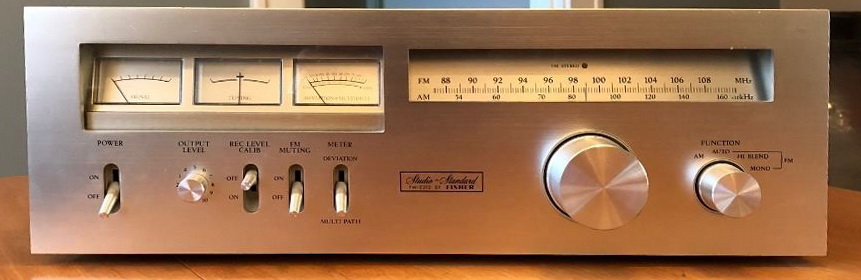
This is one of Fisher's last high-end designs for an AM-FM stereo tuner and was a serious competitor of Marantz brand. The tuner part is similar to what can be found in Fisher's top receiver, the RS-1080. Has an aluminum face panel with simple markings, 3 meters: signal level, the center of channel tuning, and deviation/multipath (switchable) on the front panel. The FM Deviation / Multipath Meter is very unique, different and definitely, I don't see on any other manufacturers. The dial is somewhat reduced in length due to the inclusion of the meters, but still easy to read. Inside has two circuit boards, one for the power supply (which includes the Deviation/Multipath circuitry) and one for the AM-FM IF MPX and audio circuits. The FM RF circuitry is in a separate shielded box along with the AM RF/Osc/Mixer tuning circuits. Has an FM front end with DGMOSFET RF amplifier stage, separate mixer, and oscillator circuits and a 5-gang mechanical tuning capacitor. It has a total of 4 ceramic IF filters (all of which are plugged into sockets) that are all 280kHz bandwidth. Since the 3-leg filters plugin, they can easily be changed to narrower bandwidth filters if desired for DX work. The LA1230 quadrature detector and LA3350 MPX ICs are also factory socket-mounted!
General information:
- Manufactured at 1977 by Fisher (Sanyo) in Japan
- 2 band analog superheterodyne receiver, MW and FM
- Coverage: MW 525kHz - 1.605MHz, FM 88.0MHz - 108.0MHz
- Antenna input impedance for FM: 300 ohms balanced and 75 ohms unbalanced,
- No preset memory for FM
- Usable sensitivity: 1.7 uV on FM mono and 4.3 uV (!) for stereo; 280uV/m on AM
- Intermediate frequencies: 455kHz for AM, and 10.7MHz for FM
- Used ICs: FM IF amplifier LA1222; FM IF detector LA1230; MPX decoder LA3350; AM IF detector HA1138; output amplifier LA3122 and for deviation/multipath CD894A and TA7120
- Signal to noise ratio: mono 80dB, stereo 75dB for FM
- Harmonic distortion: mono 0.10%, stereo 0.15% for FM
- Output frequency range on FM: 20Hz - 15kHz (+0.5...-1.5dB)
- Stereo separation (1kHz/10kHz): 50/36 dB
- Power: 110V/220V 50Hz, consumption 16W
- Dimensions: 440x140x315 mm, 10.5 kg.
- Selling price at that time of a new unit: 1089DM
- Has a very clean sound with bright bass, low noise, good channel separation
- Has a separate operational amplifier IC (LA3122) at output instead of direct signal from MPX IC
- Very good sensitivity on FM
- Has an extra meter for deviation and multipath: deviation act almost as a VU meter, and multipath makes it possible to adjust the tuner more precisely on station (when shows 0%)
- Has an additional adjustable output, adjusted from the front panel
- High Blend function: during the reception of stereo broadcast, noise possibility caused in both channels are reversed in phase to each other. With high-blend switched on, the separation in the audio high-frequency band becomes a little decreased.
- Air check calibration circuit: this circuit is to make appropriate the recording level in advance when recording FM broadcast into the tape recorder. This circuit is an RC type oscillator to be used for air check calibration with approximately 400Hz frequency. In the case of AM signal, the air check calibration is not functioning.
- Lower scale width regarding 3 meters on front
- Has 4 pcs 280kHz wide-bandwidth ceramic filters (in sockets!) - is recommended to be changed with low loss 150kHz models, all carefully paired.
Its sensibility outperforms some tuner with better specifications.
It retailed for about $250 back in 1977, which in today's dollars is roughly $890!
Fisher Studio - Standard FM-58
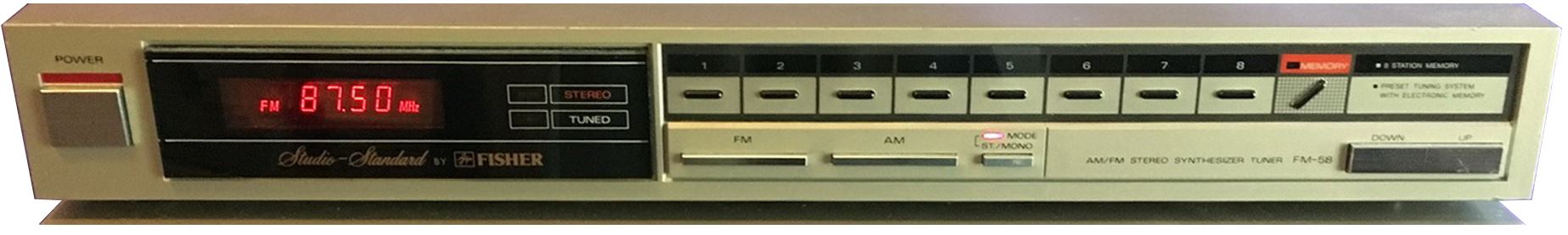
This is a 1985 middle series by Fisher (the higher grade was FM-67, the lesser grade was FM-30 or FM-35). The front panel is rather basic, showing the bands, stereo, tuning, and received frequency. There are eight preset, one memory storage, two up/down tuning, a 3 band selecting, and one stereo/mono selection buttons.
General information:
- Manufactured at 1985-85 by Fisher (Sanyo) in Japan
- 3 band analog superheterodyne receiver, MW and FM
- Coverage: LW 153-280kHz, MW 525kHz - 1.605MHz, FM 88.0MHz - 108.0MHz
- Antenna input impedance for FM: 75 ohms unbalanced (appears models with balanced 300 ohm antenna input),
- 8 random preset memory for AM-FM
- Usable sensitivity: 1.2uV on FM mono and 40uV for stereo; 300uV/m on MW and 700uV on LW
- Intermediate frequencies: 450kHz for AM, and 10.7MHz for FM
- Used ICs: FM and AM IF detector LA1260; MPX decoder LA3400; TD6104 prescaller, TD6301 display driver, TC9147 microcontroller, LC4013
- Signal to noise ratio: mono 70dB, stereo 60dB for FM, 55 dB for AM
- Harmonic distortion: mono 0.30%, stereo 0.40% for FM, 0.50% for AM
- Selectivity: 65dB on FM, 45dB on AM
- Crosstalk: 40dB on FM
- Capture ratio: 1.5dB
- AM suppression: 55dB on FM
- Pilot and subcarrier suppression: higher than 50dB on FM
- Power: via CA-38/CA-58 19Vac, consumption: 9W
- Dimensions: 400x57x207 mm, weight 1.7 kg.
- Selling price at that time of a new unit: 295 DM
- Has a pleasant sound, with warm coloration
- Sharp and brilliant display
- On FM, sensitivity is excellent
- powered only by the matching audio amplifier (CA-38 or CA-58) using a specific connector that runs on 19Vac/9W.
- One LED for tuning indicator, no signal level meter
- The whole chassis is composed of plastic, and an RF isolation metallic plate is located on the bottom.
- There are multiple places where parts (filtering capacitors) are missing, where coils are swapped out for shorts or resistors, or where variable resistors and capacitors are swapped out for fixed resistors or capacitors.
- Absence of automatic memory storage or station seeking functionality
The power transformer (17Vac/9W) was fitted, and the supply cable was changed. There is no longer a requirement for an amplifier to power the independent tuner.
General Radio Co.
On June 14, 1915, a small group of investors started General Radio Company in Cambridge, Massachusetts, near Massachusetts Institute of Technology. During the 1950s, the company moved to West Concord, Massachusetts, where it became a major player in the automatic test equipment (ATE) business. It also produced extensive lines of electrical component measuring equipment, sound and vibration measurement and RLC standards. In 1975, the company name was changed to GenRad. In 1991, a startup QuadTech was founded as spinoff of GenRad's Instrumentation division and Precision Product lines, as well as the rights to use the "GenRad" and "General Radio" names. In 2000, IET Labs acquired QuadTech.
419-A Rectifier Type Wave Meter
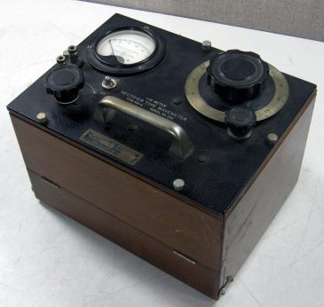
General information:
This wave-meter is a tuned circuit instrument designed for general application in experimental work within the short wave band, specifically ranging from 1 to 15 meters (20-300 MHz). Provision is established for indicating resonance through a self-contained vacuum-tube (thermionic) rectifier, which can be utilized alongside either its micro-ammeter or a pair of telephone receivers. Any of the various reaction methods can be utilized.- Manufactured at 1929 by General Radio Co., Cambridge A, Massachusetts
- Measurement method: absorption - placed in vicinity of source
- 4 ranges with 4 interchangeable inductors: 20-40MHz, 40-75MHz, 75-150MHz and 150-300MHz - all based on amplitude modulation.
- Calibration: 4 separate charts given for each range/inductor.
- Accuracy: within 1%
- Rectifier: one RCA 1G4-G triode, with 1-1.2V/40mA filament voltage (from battery)
- Power supply: 1.5V A type battery
- Dimension: 10 1/4 x 7 5/16 x 7 1/4 (HxWxD) inches.
- Net weight: 7 3/4 pounds with tube but without battery
- Serial number: 211
- Price: 100$ (remain same from 1929 till 1938 based on General Radio Catalog J and K)
Grundig
Grundig began in 1945 with the establishment of a store named Fürth, Grundig & Wurzer (RVF), which sold radios and was headquartered in Fürth, northern Bavaria. After the Second World War, Max Grundig recognized the need for radios in Germany, and in 1947 produced a kit, while a factory and administration center were built at Fürth. In 1951, the first television sets were manufactured at the new facility. At the time Grundig was the largest radio manufacturer in Europe. It grew to become one of the leading radio, TV, recorder, and other electronics goods manufacturers of Europe in the following decades of the 20 centuries. In the 1970s, Philips began acquiring Grundig AG's shares, leading to complete control in 1993. In 1998, Philips divested Grundig. In 2007, Koç Holding bought Grundig and put the brand under its home appliances subsidiary Arcelik A.S.
Grundig Yacht Boy 400 - old
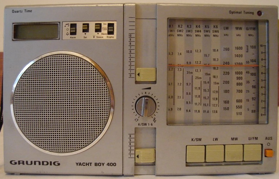
It is difficult to discover specific information on this radio because Grundig launched a digital version of the same name in 1990. Its outward design is clearly influenced by the original Sony 7600 (with the same frequency ranges and scales). The base joint of the telescopic antenna on the top edge of the gadget is retractable. The buttons for setting the time are also positioned on the top edge, on the left-hand narrow side close to the external electricity connection. There is only one earphone socket, no other connections.
General information:
- Manufactured between 1980-81 by Grundig (Radio-Vertrieb, RFV, Radiowerke), Fürth/Bayern
- IF frequency: on AM: 460kHz, for FM 10.7MHz
- Frequency ranges: FM 87.3-108.2MHz; LM 143 - 266 kHz, MW 505 - 1650 kHz, SW is from 5.85 kHz till 18.45MHz (I have Professional version).
- Signal strength indicator: just via one LED
- Frequency memories: no
- Sensitivity: no data
- Antennas: for FM and SW a telescopic aerial, for LW and MW a built-in ferrite rod, no external antenna connection
- Output power: 1W on 4 ohm, 8cm diam
- Used integrated circuits: IF AM/FM amplifier circuit AN7218
- Power supply: 5 x 1.5V UM-3 or C, and 1.5V LR44 for quartz clock; or external 7.5 Vdc
- External dimensions: 223 x 134 x 42 mm (WxHxD)
- Weight:0.7 kg (without batteries)
Good things:
- High selectivity (on all bands)
- Very balanced sound regarding built in speaker with big diameter
Difficult, problematic items:
- Very heavy, is a table top radio, is not a pocket size
- The external power supply is not standard; it requires 7.5Vdc, with the negative connection in the center of the jack.
If possible, replace capacitors with high capacity and low voltage (470uF/6.3 or 10V, 330uF/10V, 220uF/10V) with solid electrolytic types, but in general is better if you change all electrolytics.
Changed capacitors value: C61 and C75 new value is 0.47uF foil capacitor, and C71 now is 0.1uF foil capacitor.
In general a very good receiver, listenable in any kind of purpose: DX-ing, or just daily listening music.
Grundig T7500
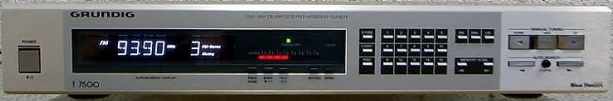
General information:
- Manufactured between 1984-86 by Grundig Portugal
- 3 bands: FM 87.5 - 108 MHz, LW 155 - 353 kHz, MW 522 - 1611 kHz
- Tuning steps: FM: 25kHz, LW and MW 1 or 9 kHz, SW 1 or 5kHz
- Sensitivity: 0.5uV on FM Mono, 20uV on FM stereo; 9.5uV for MW and 12uV for LW
- Self seek trashhold: on FM 3uV...2mV (75 ohm), on AM 100uV...10mV and on LW 200uV...20mV (both on 75 ohm)
- Preset memory: 15, and can be mixed between FM, MW and LW
- Intermediate frequencies: for FM 10.7MHz, for AM 455kHz
- IF bandwidth: on FM 130kHz, on AM 4kHz
- IF rejection ratio: for FM higher than 120dB, for AM higher than 40dB
- AM suppression: higher than 54dB at 1kHz
- Image rejection: on FM better than 120dB, on MW better than 43dB and on LW better than 63dB
- Antennas: for FM balanced 75 ohm, for LW and MW external aerial
- Capture ratio: less than 1.5dB
- Signal to noise ratio (weighted): 76dB rms
- FM stereo frequency response: 10 - 16.8kHz for -3dB, and 20 - 15kHz for -1dB
- THD: FM mono less than 0.09%, FM stereo less than 0.15% for 1kHz and 40kHz deviation
- Dynamic selectivity: mono higher than 80dB
- FM crosstalk: higher than 47dB at 10kHz, and higher than 48dB at 1kHz
- Pilot tone rejection: higher than 63dB for 19kHz, and higher tan 80dB for 38kHz
- Output: AF output 175mV - 1500mV, Level control range: -13 - +5.5dB compared to center setting (800mV). DIN record level: 0.87mV/kohm
- Used integrated circuits: FM IF TDA1576, AM IF TDA1072 and TDA1576, MPX decoder TDA1578, synthesizer DS8906N, microcomputer SC86012, display driver COP470N 3 pcs, memory MCM2802, SO459 tunoscope, signal meter UAA180, loop filter CA3140 and HEF4016, voltage regulators MC78M05
- Power consumption: 15W
- External dimensions: 450 x 80 x 330 mm (WxHxD)
- Weight: 5.2kg
- Price: 798DM at 1984
- Manual and automatic station scan via separate buttons
- Memory scan (manual dialing through stored stations)
- Comp function: Check whether set frequency already exists in station memory
- Tuning display and field strength display with LEDs
- Station short name (4-digit alphanumeric display) can be stored for each fixed station
- RAM memory (non-volatile memory) for station settings
- High selectivity on FM - 0.5uV!
- Usage of special antenna connector for AM
- Just one IF bandwidth, no switch for wide and narrow mode
- Without ferrite rod and with special AM antenna socket the listening of AM (MW and LW) is difficult
- Manufactured between 1986-89 by Grundig Portugal
- IF frequency: is a double conversion receiver on AM: 54.4MHz and 450kHz, for FM 10.7MHz
- Operation modes: A1, SSB, AM (A3), AM-Sync and FM (F3)
- Frequency ranges: FM 88-108MHz; LM 148 - 352 kHz, MW 513 - 1611 kHz, SW is from 1612 kHz till 26.1MHz (I have Professional version).
- Frequency display (digital) resolution: 1kHz
- Signal strength indicator: LCD bar graph, 16 segments
- Tuning steps: FM: 25kHz, AM/USB/LSB/Synchronous detection; tuning steps 9kHz (scan), 1kHz (manual tuning)
- Frequency memories: 24 programmable memories
- Sensitivity: AM (A3) less than 2 uV, SSB less than 1 uV, for FM...
- Antennas: for FM and SW a telescopic aerial or 75 ohm unbalanced connector for external antenna, for LW and MW a built-in ferrite rod
- Output power: 1.5W from main, and 1W via battery operation
- Used integrated circuits: TDA4150 FM IF, SAA1057 PLL synthetiser, TDA4100 AM IF, MC14066 4 CMOS switch, TDA1904G audio amplifier, MC14094 switching stage, uPD7503 G-370-11 microcontroller
- Power supply: 6 x 1.5V UM-2 or C, and 3 x 1.5V UM-3 or AA for quartz clock; or external 12 Vdc; or via 100-127V/220-240 Vac build in mains power
- External dimensions: 304 x 180 x 71 mm (WxHxD)
- Weight:2.1 kg (without batteries)
- No more technical parameters are available about this radio
- Price in 1985: 451DM, or in 1989 399USD
- High selectivity (excepting LW)
- On the back you can observe the fold-down table-stand support
- Very balanced sound regarding built in speaker with big diameter
- Very heavy, is a table top radio, is not a pocket size
- Battery eater regarding high consumption - but with external or built in main supply is perfect
- Manufactured between 1992-96 by Grundig Portugal
- IF frequencies: is a double conversion on AM 54.4MHz and 450kHz, and FM 10.7MHz
- Operation modes: A1, SSB, AM (A3), AM-Sync and FM (F3)
- Frequency ranges: FM 87.5-108MHz; LM 150-353kHz, MW 522-1611kHz, SW (1.612 - 30MHz). For Italian version the SW is just till 26.1MHz.
- The list of receivable SW bands:
- 160m: 1815 - 1890 kHz
- 120m: 2300 - 2498 kHz
- 90m: 3200 - 3400 kHz tropical
- 80m: 3500 - 3800 kHz amateur
- 75m: 3900 - 4000 kHz
- 60m: 4750 - 5060 kHz tropical
- 49m: 5950 - 6200 kHz
- 41m: 7100 - 7300 kHz
- 40m: 7000 - 7099 kHz amateur
- 31m: 9500 - 9900 kHz
- 30m: 10100 - 10150 kHz amateur
- 25m: 11650 - 12050 kHz
- 22m: 13600 - 13800 kHz
- 20m: 14000 - 14350 kHz amateur
- 19m: 15100 - 15600 kHz
- 17m: 17065 - 17170 kHz amateur
- 16m: 17550 - 17900 kHz
- 15m: 21000 - 21449 kHz amateur
- 13m: 21450 - 21850 kHz
- 12m: 24890 - 24990 kHz amateur
- 11m: 25650 - 26100 kHz
- 10m: 28000 - 29700 kHz amateur
- Frequency display (digital) resolution: 100Hz
- IF filters bandwidth: on Wide is 6.8kHz (-6dB), on Narrow 4kHz (-6dB)
- Signal strength indicator: LCD bar graph, 16 segments
- Tuning steps: on FM 25kHz, AM/USB/LSB/Synchronous detection; tuning steps 9kHz (scan), 1kHz (manual tuning), 100Hz (manual SSB/Synch)
- Used ICs: AM-FM IF LA1205, synch. demodulator CX857, Pll CX7961A - 2 pcs, mixer uPC1037HA - 2 pcs, RDS decoder SAF7579, voltage regulator LP2951ACN, controller uPD75516, eeprom X24C16P3, display driver uPD7225 - 2 pcs, MPX decoder LA3361, power amplifier TBA820M - 2 pcs
- Frequency memories: 96 fixed + 512 to 2048 programmable memories (can be extender with 3 more CMOS EEPROMs with 2048x8bits 3.3V type, sockets already built in the set) - this means expanding the storage to 265 pages with 8 alternative frequencies per page
- Sensitivity: AM (A3) less than 2 uV, SSB less than 1 uV, for FM...
- Antennas: for FM and SW a telescopic aerial (internal preamp for SW), for LW and MW a built-in ferrite rod
- Output power: 1.5W via built in 6" 8 ohm speaker, or external speakers 2x1.5W from main (peak power 2x3W), and 2x1W via battery operation
- Headphone impedance: 32-2000 ohm, with 3.5mm jack
- Used integrated circuits:
- Stereo: just via headphones
- Power supply: 4 x 1.5V UM-1, LR20 or D type batteries (estimated life approx. 90 hours), or 9-12 V DC external power supply (delivered with set: NR90 100-127V/220-240V mains unit). NiCd charger is built into the set for 4000mA type accumulators! Built in a recharging lithium battery for data protection
- External dimensions: 304 x 178 x 66 mm (WxHxD)
- Weight:2.0 kg (without batteries)
- No more technical parameters are available about this radio
- Price in 1992: 599 USD
- High selectivity (excepting LW)
- RDS (just the station's name), no Radio Text (which did not exist at that time)
- Very balanced sound regarding built in speaker with big diameter
- Signal level, band, and clock indication on the display
- Very heavy, is a table top radio, is not a pocket size
- Battery eater regarding high consumption - but from wall plug is perfect
- An external charger is highly recommended, unless you have almost endless time. Otherwise, a full charge with the NR-90 power supply of 4000mAh accumulators takes a whopping 40 hours!
- Manufactured between 1995-97 by Grundig probably in Far East (China?)
- 4 bands: FM 87.5 - 108 MHz, LW 144 - 353 kHz, MW 522 - 1710 kHz, SW 1.711 - 30 MHz in total 20 SW bands (the tunning is continuous with steps)
- Shortwave bands by lengths for SW (20 bands):
- 90m: 3200 - 3400 kHz tropical
- 80m: 3500 - 3800 kHz amateur
- 75m: 3900 - 4000 kHz
- 60m: 4750 - 5060 kHz tropical
- 49m: 5950 - 6200 kHz
- 41m: 7100 - 7300 kHz
- 40m: 7000 - 7100 kHz amateur
- 31m: 9500 - 9900 kHz
- 30m: 10100 - 10150 kHz amateur
- 25m: 11650 - 12050 kHz
- 22m: 13600 - 13800 kHz
- 20m: 14000 - 14350 kHz amateur
- 19m: 15100 - 15600 kHz
- 17m: 17065 - 17170 kHz amateur
- 16m: 17550 - 17900 kHz
- 15m: 21000 - 21449 kHz amateur
- 13m: 21450 - 21850 kHz
- 12m: 24890 - 24990 kHz
- 11m: 25650 - 26100 kHz
- 10m: 28000 - 29700 kHz amateur
- Tuning steps: FM: 50kHz, LW and MW 1 or 9 kHz, SW 1 or 5kHz
- Preset memory: 40 random memory locations
- Intermediate frequencies: for FM 10.7MHz, for AM 55.85MHz and 450kHz
- Antennas: for FM and SW a telescopic aerial, for LW and MW a built-in ferrite rod
- Used integrated circuits: FM frontend LA1185, AM/FM IF LA1205, MPX decoder LA3335, stereo power amplifier LA4550, PLL sinthetiser LC7216, controller and display driver LC5863H, voltage regulators LA5005M, RH5VA50AA, RH5VA45AA, comparator LA6393M
- Output power: 320mW via a built-in 32 ohm loudspeaker
- Stereo: just via headphones
- Power supply: 9 V by 6 pcs of AA-type batteries or 9 V DC external power supply (negative at the center of the connector!)
- External dimensions: 178 x 120 x 39 mm (WxHxD)
- Weight:590 g (without batteries)
- No more technical parameters are available about this radio
- High selectivity (excepting LW)
- Scan up and down
- Good sound despite of the small speaker diameter
- Signal level, band, and clock indication on the display
- No tuning knob, just up/down tuning buttons
- Heavy regarding 6 pcs of AA batteries
- No external antenna connectivity
- No SBB reception possibility, for this reason, cannot be used efficiently the whole SW band
- Different output capacitor values at the output of power amplifier: 470uF for speaker and right headphone, and for the left headphone 220uF (via 47ohm resistor for both headphone outputs).
- Manufactured between 1997-98 by Grundig in Portugal (that time part of Philips)
- 4 bands: FM 87.5 - 108 MHz, MW 520 - 1710 kHz with 10kHz steps for America, and 522 - 1620 kHz for the rest of the World, SW1 2.30 - 7.40 MHz and SW2 9.40 - 26.10 MHz, in total 13 SW bands
- Shortwave bands by lengths for SW1 (6 bands):
- 120m: 2300 - 2550 kHz
- 90m: 3150 - 3450 kHz
- 75m: 3850 - 4050 kHz
- 60m: 4700 - 5150 kHz
- 49m: 5750 - 6300 kHz
- 41m: 7050 - 7400 kHz
- Shortwave bands by lengths for SW2 (7 bands):
- 31m: 9400 - 10050 kHz
- 25m: 11500 - 12200 kHz
- 22m: 13500 - 13900 kHz
- 19m: 14950 - 15700 kHz
- 16m: 17400 - 18000 kHz
- 13m: 21300 - 21950 kHz
- 11m: 25600 - 26100 kHz
- Tuning steps: FM: 50kHz, MW 9/10 kHz, SW 5kHz
- Preset memory: in total 20 - 5 for FM and, 5-5 for AM (5 for MW, 5 for SW1, and 5 for SW2)
- Intermediate frequencies: for FM 10.7MHz, for AM 450kHz
- Antennas: for FM and SW a telescopic aerial, for MW a built-in ferrite rod
- Output power: 250mW
- Used integrated circuits: FM frontend TA7358, AM/FM IF and MPX decoder TA8132, stereo power amplifier TA7376, controller and display driver TC9316F, voltage regulators LA5002M, RH5VA20C, RH5RL25AA
- Stereo: just via headphones (the impedance of delivered headphone was 32 ohms)
- Power supply: 4.5V by 3 pcs of AA type batteries or 4.5V DC external power supply
- External dimensions: 142 x 92 x 35 mm (WxHxD)
- Weight: 330 g
- Sales price in 1998 was 220 DM.
- No more technical parameters are available about this radio
- Very beautiful design, easy operation, all buttons deepened, but easy to be pushed
- Is a stereo radio via headphone
- Nice snap-on leader case. When is closed, the speaker, the antenna, and the power button are free. The case can be folded back and became a support for the tilted radio
- Direct digital keypad tuning
- Can be selected the required SW band by name of band wavelength/meter
- Has a Lock switch, protecting during travel or by mistake and powering on
- Low preset memory, just 5-5 locations for FM, MW, SW1, and SW2
- No continuous tuning, in Continuous mode the radio jumping from the end of one of commercial bands to the beginning of the next commercial band (ex from end of 120m band, 2550kHz will jump to beginning of 90m band, to 3150kHz) - means the tuning is not really continuous.
- The display lamp is activated just till the Lamp button is pressed, no temporization
- The sensitivity on FM (no active input filter) and on MW (internally has a very small ferrite rod) is acceptable, but on the SW band is very poor
- In AM mode has just a single conversion IF, which means on the AM the reception is very noisy
- The tuned indicator on the display shows just the radio is tuned to the station frequency, if we are near, no help in which direction we should go
- Manufactured between 2007-2015 by Grundig in China (Sangean?)
- 4 bands: FM 87.5 - 108 MHz, MW 526.5 - 1606.5 kHz, LW 148.5 - 283.5 kHz, and SW 3.90 - 21.85 MHz in total 9 SW bands
- Shortwave bands by lengths for SW (9 bands):
- 75m: 3900 - 4000 kHz
- 49m: 5900 - 6200 kHz
- 41m: 7100 - 7500 kHz
- 31m: 9500 - 9900 kHz
- 25m: 11650 - 12050 kHz
- 22m: 13600 - 13800 kHz
- 19m: 15100 - 15600 kHz
- 16m: 17500 - 17900 kHz
- 13m: 21400 - 21850 kHz
- Preset memory: no
- Intermediate frequencies: for FM 10.7MHz, for AM 450kHz
- Antennas: for FM and SW a telescopic aerial; for MW a built-in ferrite rod
- Output audio power: 100mW on 4 ohms
- Used integrated circuits: AM/FM tuner, IF and MPX decoder TA2111N; stereo power amplifier TDA2822
- Stereo: just via headphones (the impedance of delivered headphone was 32 ohms)
- Power supply: 3V via 2 pcs of AA/LR6/AM3 type batteries or 3-6V DC/200mA external power supply
- External dimensions: 150 x 85 x 34 mm (WxHxD)
- Weight: 250 g
- Sales price in 2007 was 89$.
- No more technical parameters are available about this radio
- Clear sound
- Very good sensibility on FM, good on MW
- Case snaps into magnetic press studs, easy to remove or attach
- Stylish look
- Low battery consumption
- Case is unfortunately made of plastic, not leather
- No signal strength indicator, just stereo indication, when the headphone is plugged in
- Sound is very muffled if you don't fold back the cover
- The speaker has a small diameter compared to the chassis, hence the sound lacks bass.
- Manufactured by Harman Kardon in USA at 1991
- Digital 2 bands (MW-FM) PLL radio,
- 24 memory presets, which can be mixed between AM and FM
- Coverage: MW 520kHz - 1.710MHz, FM 87.5MHz - 108.0MHz
- Usable sensitivity: 20uV on AM, 1.0uV on FM (mono) and 17.7uV for stereo - via a very sensitive JFET FM tuner
- FM IF IC: LA1235, AM tuner IC: LA1245, stereo decoder: LA3450, PLL with prescaller: TC9227P, uController: TC9301AN, interface for I/O port: TC9173P, LED driver for signal strength: BA6124, FL tube display driver: TB2104F
- Output frequency range: 20Hz - 15kHz (-1...+0.5dB)
- Signal/noise ratio: AM 53dB, FM 82dB mono, 78dB stereo
- THD: on FM 0.06% for mono, and 0.08% for stereo
- Stereo separation: 50dB
- Alternate Channel Selectivity (FM): 80dB with Active tracking mode
- Adjacent Channel Selectivity: on FM 30dB with Active tracking mode, on AM 55dB
- Line output impedance: 10 kohm
- Line output levels: 440mV in AM mode, 1.1 V in FM mode
- Antenna input impedance for FM: 75 ohms for both. Selection of input via relay
- Power: 230V/50Hz, Consumption: 9W
- Dimensions: 443x73x328mm, 3.4kg
- Has a very clean sound, low noise, good channel separation, good readable FL display, and good "Active Tracking" which has a function of "narrow" IF.
- Has 2 FM antenna inputs, selectable from the front panel
- Discrete output amplifier instead of an operational amplifier IC
- Is impressive the quality of electrical parts used, especially in case of solid capacitors
- Memory is organized like 3 x 8 = 24 positions (A:1-8, B:1-8, C:1-8). Should be more natural 3x10 = 30.
- Has no RDS (in 1991 was not so common).
- In the case of tracking/fine-tuning, the display does not show the base frequency modification in numbers, just with arrows in +/-2 marks.
- Manufactured by Hitachi Ltd., Tokyo, Japan between 1977-1979
- Analog 2 bands (MW-FM) superheterodyne radio,
- No memory presets
- Coverage: MW 530kHz - 1.605MHz, FM 88.0MHz - 108.0MHz
- Usable sensitivity: 40uV on MW (250uV/m with bar antenna) and 2.0uV on FM (no data for FM stereo)
- FM/AM IF IC: uPC27C (EGC1124), stereo decoder: HA1156WZ
- Output frequency range: 20Hz - 15kHz (+1.0dB...-1.0dB)
- Signal/noise ratio: FM 75dB (no data for FM stereo), 45dB on AM
- THD: on FM 0.15% for mono, and 0.4% for stereo, both at 400Hz
- Image rejection: 50dB on FM, 56 dB on AM (1kHz)
- IF rejection: 90dB on FM, 38dB on AM
- Selectivity: 65dB (+-400kHz) on FM, 35dB on AM (+-10kHz)
- Capture ration: 1.5dB
- Stereo separation: 40dB (1kHz)
- Alternate Channel Selectivity (FM): 50dB
- Line output impedance and level: 4.7 kohm/300mV (400Hz, 30% modulation)
- Antenna input impedance for FM: 75 ohms unbalanced or 300 ohms balanced
- Power: 100-120V or 220-240V 50/60Hz - selectable, Consumption: 9W
- Dimensions: 390x143x369mm (WxHxD)
- Weight: 5.5kg
- Price at 1978: 485 DM
- Good sensibility on FM, clean sound, low noise
- Easy to tune using the 2 meters
- Minimalist and beautiful front panel
- The ferrite rod cannot be rotated, just move apart or closer to the chassis. This can make difficult the precise ideal adjustment of AM stations (with low hum and maximum signal level)
- Manufactured by Hitachi Ltd., Tokyo, Japan at 1981
- Analog 2 bands (MW-FM) superheterodyne radio (FT-3500L are with 3 bands, including the LW),
- No memory presets
- Coverage: MW 530kHz - 1.605MHz, FM 88.0MHz - 108.0MHz
- Usable sensitivity: 15uV on MW and 1.0uV on FM mono and 23uV for FM stereo - via a very sensitive MOSFET FM tuner
- FM IF IC: HA12412, AM tuner IC and IF amplifier: AN217, stereo decoder: HA1196
- Output frequency range: 20Hz - 12kHz (+2.0dB...-2.0dB)
- Signal/noise ratio: FM 77dB for mono, 70dB for stereo
- THD: on FM 0.1% for mono, and 0.25% for stereo
- Stereo separation: 45dB
- Alternate Channel Selectivity (FM): 50dB
- Line output impedance and level: 6.8 kohm/550mV
- Antenna input impedance for FM: 75 ohms unbalanced or 300 ohms balanced
- Power: 220-240V 50/60Hz, Consumption: 6W
- Dimensions: 435x83x253mm (WxHxD), 3.4kg
- Good sensibility on FM, clean sound, low noise
- The scale is shown by a rectangular red LED
- Very easy operation
- No signal strength indicator, just the 2 lateral LEDs light intensity can be used from the cursor
- The output frequency range seems to be narrow, just 30-12kHz with high deviation, but the sound is pleasant
- Has no scale light, which means in dark you cannot see where are you on the scale
- Manufactured by Hitachi Ltd., Tokyo, Japan between 1978-1981
- Digital one band FM tuner,
- 6 memory presets
- Coverage: 88.0MHz - 108.0MHz
- Usable sensitivity: 0.9uV on FM mono (no level mentioned for FM stereo) - via a very sensitive MOSFET FM tuner
- FM IF IC: HA11211, FM IF amplifier HA1211, MPX stereo decoder: HA11223, audio output buffer amp HA1452, prescaller TD6102, crystal osc and counter TC9123, controller TC9124, decoder TC5022 and display driver TC5066 (2 pcs),
- Output frequency range: 10Hz - 15kHz (+1.0dB...-1.5dB)
- Signal/noise ratio: FM 75dB for mono, 72dB for stereo
- THD: on FM 0.12% for mono, and 0.15% for stereo
- Stereo separation: 50dB
- Image rejection ratio: 70dB
- IF rejection ratio: 85dB
- Alternate Channel Selectivity (FM): 70dB
- Line output impedance and level: 600 ohms, level not known
- Antenna input impedance for FM: 75 ohms unbalanced (DIN and wire) or 300 ohms balanced
- Power: 220-240V 50/60Hz, Consumption: 19W
- Dimensions: 435x78x369mm (WxHxD), 6,1kg
- Price in 1981: 798 DM
- Good sensibility, clear sound, low noise
- Has an attenuator for very strong local stations
- Easy operation, clear VFD display
- Has 2 independent power systems: one for the analog tuner section, and one for the digital section, both with 1-1 transformer.
- No tunning indicator, but the stations are precisely found on the transmission frequency
- The input signal attenuation switch is on the backside - is uncommon to switch it on or off during DX-listening.
- Nowadays 6 preset stations are not enough
- Manufactured at 1980 by JVC - Victor Company of Japan Ltd. at Yokohama
- 3 band analog superheterodyne tuner LW, MW and FM
- Coverage: LW 150 kHz - 360 kHz, MW 520kHz - 1.710MHz, FM 87.5MHz - 108.0MHz
- Antenna input impedance for FM: 300 ohms balanced, 75 ohms unbalanced,
- No preset memory for FM
- Usable sensitivity: 80uV on LW (external aerial), 50uV on MW (ferrite bar), 0.9 uV on FM mono and 22.5 uV for FM stereo
- Intermediate frequencies: 450kHz for AM, and 10.7MHz (exactly 10.67MHz, blue marked filter) for FM
- AM/FM ICs: HA1197 AM tuner IC, HA11225 FM IF system, uPC1161C MPX decoder IC and LB1416S as a signal indicator.
- Output frequency range: 40Hz - 15kHz (-0.5...+0.5dB)
- Power: ~220V/50Hz, consumption 12W
- Output power: 600mV/3.3kohm
- Dimensions: 420x108x313mm, 4 kg.
- Manufactured between 1982 - 1984 by Victor Company of Japan
- 3 band analog PLL tuner LW, MW, and FM
- Coverage: LW 150 - 350 kHz, MW 525 - 1605 kHz, FM 88 - 108 MHz
- Antenna input impedance for FM: 300 ohms balanced, 75 ohms unbalanced,
- No preset memory for FM
- Usable sensitivity: 30uV on MW, 100uV on LW, and 0.9 uV on FM (mono) and 44 uV for stereo
- Intermediate frequencies: 450kHz for AM, and 10.7MHz for FM
- AM tuner IC: LA1245 amp, osc, IF and det; FM det. HA1137W; stereo decoder (MPX) uPC1161C3; signal indicator LB1416
- Output frequency range: 30Hz - 15kHz (+0.5dB...-0.8dB)
- Signal/noise ratio: AM 50 dB, FM 74dB mono, 67dB stereo
- THD: 0.2% in FM mono, and 0.3% in stereo at 1kHz; 0.3% on AM
- Stereo separation: 37dB at 1kHz
- Channel balance: no data
- Power: ~220V/50Hz, consumption 7W
- Output power: 800mV/3.3kohm
- Dimensions: 435(W) x 77(H) x 299mm (D), 2.9 kg.
- Manufactured at 1979-1981 by Trio-Kenwood Co., Meguro-ki, Tokyo, Japan
- 2 band analog superheterodyne tuner, MW and FM
- Coverage: MW 510kHz - 1.640MHz, FM 87.5MHz - 108.0MHz
- Antenna input impedance for FM: 300 ohms balanced and 75 ohms unbalanced,
- No preset memory for FM and AM
- Usable sensitivity: 0.8 uV on FM mono, 25uV on FM stereo; 9uV on AM
- Intermediate frequencies: 455kHz for AM, and 10.68MHz
- Used ICs: AM tuner HA1197, FM IF amplifier LA1222 and TA7060P, FM IF system HA1137, balanced modulator MC1496, pulse count detector TR4010A, PLL stereo demodulator HA11223W, op. amplifiers HA1457.
- Signal to noise ratio: mono 84dB, stereo 80dB for FM, and 55dB for AM
- Harmonic distortion: mono 0.05%, stereo 0.07% for FM, and 0.5% for AM
- Output frequency range: 30Hz - 15kHz (-0.3...-0-5dB)
- Power: ~110-120/220-240V/50Hz, consumption 20W
- Output: fix 0.75V/2.5kohm or variable 0-1.3V/1.5kohms; multipath output: vertical 0.02V/1kohm and horizontal 0.35V/10kohm
- Dimensions: 440x153x402mm, 7.6 kg.
- Extremely clear sound
- High sensibility and selectivity on FM, but also the AM is very good
- Nice adjustment using the 2 instruments
- Variable output signal level, adjusted from front panel
- Instruments illumination is very weak
- Lack of bass
- No any data can be found about TR4010A pulse count circuit, made for Trio-Kenwood
- Manufactured by Trio-Kenwood Corp., in Japan between 1980-82
- Analog, just FM band tuner with 4 gangs
- No memory presets
- Coverage: 87.5MHz - 108.0MHz
- Usable sensitivity on 75ohm antenna input: 0,6uV on FM mono and 22uV for FM stereo
- Used ICs (in total 9): SC114 as an oscillator and mixed in tuner section; TA7060 opamp as IF signal amplifier; HA1137W as FM IF system; AN610 balanced modulator circuit; TR4010A pulse count detector; AN6135 pop-noise canceller; HA12016 FM MPX decoder, AN6551 opamp as record signal calibrator and AFC; M51903L as signal level indicator for LEDs.
- Output frequency range: 30Hz - 15kHz (+0.2dB...-0.8dB)
- Signal/noise ratio: FM mono 83dB, FM stereo 80dB
- THD: on FM 0.07% for mono, and 0.12% for stereo
- Stereo separation: 47dB
- Channel balance: 1.5dB
- Alternate Channel Selectivity (FM): 75dB
- Line output impedance and level: 3.3 kohms/300mV
- Antenna input impedance for FM: 75 ohms or 300 ohms
- Power: 220V/50Hz, Consumption: 11W
- Dimensions: 440x78x333mm, 4.5kg
- Very clean sound with low distortion, and has a high signal to noise level ratio (thank to pulse count detector)
- Good sensibility
- Two 75ohms antenna inputs: for coaxial cable and wire
- Has a Postdetection Filter to eliminate HD FM radio noise (used in America)
- No tunning meter, just the servo lock - in the case of stations with low a signal is difficult to adjust using just one Tuned/Lock LED as feedback.
- The scale is not so easy to read in the dark
- No narrow/wide IF filter selector
- Manufactured by Trio-Kenwood Corporation in Japan between 1984-1985
- Digital 2 bands (MW-FM) PLL radio,
- 16 memory presets:8 for FM and 8 for AM
- Coverage: MW 522kHz - 1.611MHz; FM 87.5MHz - 108.0MHz
- Adjusting steps: MW 9 kHz; FM 50 kHz for EU version
- Usable sensitivity: 10uV on MW, 0.7uV (in some catalogs 0.95uV) on FM mono and 28uV for FM stereo
- FM IF system IC: LA1231NS; AM tuner IC: LA1245; MPX decoder uPC1223C; Prescaler: TD6104P; PLL controller TC9157P; FL display driver: TD6301AP; FM IF amplifier: uPC1163H; pop-noise canceller AN6135; signal level LED driver AN6882; analog multiplier NJM4200D; operational amplifiers NJM4558D, NJM45600-N; voltage regulator uPC78M05H
- Output frequency range: 20Hz - 15kHz (0.0dB...-+0.5dB)
- Signal/noise ratio: AM 52dB, FM 88dB mono, 76dB stereo
- THD: on FM in Wide mode 0.004% for mono and 0.008% for stereo, and in narrow mode 0.02% for mono, and 0.04% for stereo at 1 kHz
- Stereo separation: 55dB on audio band (50 Hz ... 10kHz), and 70 dB at 1 kHz
- Line output level: on FM 0.6V/ 1.8kohms, on AM 180 mV/ 1.8kohms
- Antenna input impedance for FM: 75 ohms unbalanced
- Power: 120/220V 50/60Hz (selectable at plug-in cable with a cover), Consumption: 19 W
- Dimensions: 440x64x317mm, 3.8kg
- High-quality electrical parts used
- Very good selectivity and sensitivity on AM (10uV), excellent AM section, very immune to interference/static
- Variable AM IF band control
- Dual transformer for circuits isolation
- Very low distortion on FM (0.004% in stereo wide mode), good stereo separation (68dB) and high signal/noise ratio (88dB)
- Has a Postdetection Filter to eliminate HD FM radio noise (used in America)
- In stereo mode, once the stereo signal is lost, the unit automatically mutes the audio instead of defaulting to mono which can be annoying.
- In AM mode is better if you switch to Mono mode (no mute), because the station sound intermittently is broken in case of the weak signal.
- Manufactured by Kenwood in Japan between 1987 to 1990
- Digital 3 bands (MW-FM) PLL radio without RDS capability,
- 20 random access memory presets, organized in 10+10
- Coverage: LW 153kHz - 281kHz, MW 531kHz - 1.602MHz, FM 87.5MHz - 108.0MHz
- Channel space: 1kHz for LW, 9kHz for MW, and 50kHz for FM
- Intermediate frequency: 450kHz for AM and 10.7MHz for FM
- Usable sensitivity: 10uV or 350uV/m on AM, 0.95uV on FM mono, and 25uV for FM stereo
- Integrated circuits: FM IF amplifiers BA401 (2 pcs), FM IF IC: LA1235, AM IF IC: LA1245; stereo decoder: LA3401, PLL freq. synthesizer: LM7001, electronic tuning controller: uPD7538AC-045; FL display driver: LB1241, signal level LB1493, 3 terminal power regulators: AN7805F, uPC78L10J (2pcs), Operational amplifiers: M5223P (3 pcs), M5218P, NJM2901N, band selector LA7910, digital IC: uPD4013 D-flip-flop for switches, and uPD4069UBC inverter
- Output frequency response on FM: 20Hz - 15kHz (+0.5...-0.5dB)
- Signal/noise ratio: AM 52dB, FM 88dB mono, 76dB stereo
- THD: on FM 0.1% for mono, 0.12% for stereo at 50...10kHz, on AM 0.3%
- Stereo separation: 55dB at 1kHz, 40dB at 50...10kHz
- Alternate channel selectivity: 60dB on Wide, 90dB on Narrow
- Antenna input impedance for FM: unbalanced 75 ohms, for AM: loop antenna connector and an external antenna connection possibility
- Output signal level/impedance: 0.18V on AM on 400Hz, and 0.6 V on FM at 1kHz, 3.3kohm
- Power: 220V/50-60Hz, consumption: 13W
- Dimensions: 440x78x317mm, 3.5kg
- Has a very clean sound with an extremely low noise level, low distortion,
- Big FL display
- Wide and narrow IF filters selection possibility for FM
- No mono/stereo switch - is automatically activated via manual/auto-scanning
- No fuse on primer circuit of transformer - recommended being additionally inserted. Has just thermal protection
- Manufactured by Kenwood Corporation in Japan between 1989 to 1990
- Digital 3 bands (MW-FM) PLL radio without RDS capability,
- 20 random access memory presets, organized in 10+10 (A and B page)
- Coverage: LW 153kHz - 281kHz, MW 531kHz - 1.602MHz, FM 87.5MHz - 108.0MHz
- Channel space: 1kHz for LW, 9kHz for MW, and 50kHz for FM
- Intermediate frequency: 450kHz for AM and 10.7MHz for FM
- Usable sensitivity: 10uV or 350uV/m on MW, 10uV or 600uV/m on LW, 0.7uV on FM mono, and 25uV for FM stereo
- Integrated circuits: FM IF amplifiers BA401 (2 pcs), FM/AM IF control and detection: LA1266, AM/FM power selector: LA7910, PLL synthesizer: LA7001, mute control: uPD4069, narrow/wide switch and driver: uPD4013 and M5223, signal check: M5218, T-meter comparator: M5218, FM IF amplifier/buffer: uPC1163, stereo MPX decoder: LA3401, output buffer: NJM4560D, microcontroller: uPD7538AC-045; FL display driver: LB1241, signal meter driver: LB1433N, 3 terminal power regulators: uPC7805HF, uPC78L10J (4pcs)
- Output frequency response on FM: 20Hz - 15kHz (+0.5...-0.5dB)
- Signal/noise ratio: MW 52dB, LW 50dB, FM 78dB mono and 67dB stereo
- THD: on FM 0.07% for mono, 0.2% for stereo at 50...10kHz, on AM 0.3%
- Stereo separation: 52dB at 1kHz, and 42dB at 6.3kHz
- Alternate channel selectivity: 75dB on Narrow
- Image rejection ration: 82dB at 98MHz
- IF rejection ratio: 110dB at 98MHz
- Antenna input impedance for FM: unbalanced 75 ohms, for AM: loop antenna connector and an external antenna connection possibility
- Output signal level/impedance: 0.18V on AM on 400Hz, and 0.6 V on FM at 1kHz, 3.3kohm
- Power: 220V/50-60Hz, consumption: 15W
- Dimensions: 440x98x318mm, 4.3kg
- Price at 1989: 495DM
- Has a very clean sound with an extremely low noise level, low distortion,
- Big FL display
- Has output buffer after MPX circuit
- Wide and narrow IF filters selection possibility for FM
- No mono/stereo switch - is automatically activated via manual/auto-scanning
- No fuse on primer circuit of transformer - recommended being additionally inserted. Has just thermal protection. The radio is switched ON from the secondary side of the transformer.
- Manufactured by Kenwood Portugal at 1992-1993
- Digital 3 bands (LW-MW-FM) PLL radio,
- 30 memory presets, which can be mixed between AM and FM
- Coverage: LW 153 - 281kHz, MW 520kHz - 1.710MHz, FM 87.5MHz - 108.0MHz
- Usable sensitivity: 22uV on LW, 13uV on MW (400uV/m), and 0.7uV on FM (mono) and 22uV for stereo - via a very sensitive JFET FM tuner
- AM/FM Tuner System IC: LA1266, stereo decoder: AN7470, direct PLL frequency Synthesizer IC: LM7001, uController and FL tube driver: CXP5014, LED driver for signal strength: LB1433N, + M5223 and XRA10393 opamps.
- Output frequency range: 30Hz - 15kHz (+0.5...-2dB)
- Signal/noise ratio: LW 47dB, MW 50dB, FM 68dB mono, 63dB stereo
- THD: on FM 0.15% for mono, and 0.4% for stereo, on AM 0.5%
- Stereo separation: 48dB
- Line output impedance: 3.3 kohm
- Line output levels: 180 mV in AM mode, 0.6 V in FM mode
- Antenna input impedance for FM: 75 ohm
- Power: 230V/50Hz, Consumption: 10W
- Dimensions: 440 x 79 x 264 mm, 2.6 kg
- Very good sensitivity on FM (0.7uV) and AM: 13uV on MW and 22uV on LW
- Used components were good quality (at that time).
- Memory is organized like 3 x 10 = 30 positions, but from first position cannot be selected just 9 (the 0 button can be used just with 1, 2 or3). With this, I can say just 9 stations can be selected directly on the first page.
- The display is situated too deep, cannot be seen just from a narrow-angle from the front side.
- The transformer is always connected, and the radio is switched electronically with push-button or via remote controller -> extra consumption.
- The mainboard is difficult to be taken out for repair/modification, because of short deepness (just 264mm): connectors are mounted on PCB and screwed to the rear panel, and the FL display on the front, mounted also on PCB are too deep in the front cover. To remove it is necessary to remove the back or the front of the tuner.
- No narrow or wide FM IF selection possibility.
- Manufactured between 1978-1979 by Lux Corporation in Japan
- 2 band analog superheterodyne receiver, MW and FM
- Coverage: MW 525kHz - 1.605MHz, FM 87.5MHz - 108.0MHz
- Antenna input impedance for FM: 300 ohms balanced and 75 ohms unbalanced (terminal and also with DIN connector),
- No preset memory for FM
- Usable sensitivity: 0.9 uV on FM mono and 22 uV for stereo; 250uV/m on AM
- Intermediate frequencies: 450kHz for AM, and 10.73MHz for FM
- Used ICs: FM IF system LA1231; AM tuner: HA1197; MPX decoder uPC1173C; signal level LED driver BA656, operational amplifiers for CLL and audio output buffer NJM4558D
- Signal to noise ratio: mono 75dB, for stereo no specified FM
- Muting threshold: 5-300uV
- Harmonic distortion: mono 0.08%, stereo 0.15% for FM at 1kHz
- Output frequency range on FM: 30Hz - 15kHz (+1...-1dB)
- Output voltage and impedance: 1 V on FM and 0.3V on AM / 100 ohms
- Stereo separation: 48dB at 1kHz
- Power: ~220V/50Hz, consumption 10W
- Dimensions: 438 (W) x 84 (H) x 331 (D) mm, 6.5 kg.
- Beautiful minimalist front panel, warm and very clear sound
- Closed Loop Lock, which makes it easy to tune exactly on station the tuner
- The signal-LEDs are deep in panel, can be seen just from certain angles
- No tune indicator, just the signal strength
- Manufactured by Marantz in Japan between at 1979-1982
- Digital 2 bands (MW-FM) PLL radio (exist also a 3 band version, with LW named ST 450L),
- No preset memory
- Coverage: MW 531kHz - 1.602MHz, FM 87.5MHz - 108.0MHz
- Usable sensitivity: 10uV(!) on MW and 0.9uV on FM mono and 20uV for FM stereo - via a very sensitive MOSFET FM tuner
- FM IF IC: LA1231N, AM tuner IC: LA1240, stereo decoder: HA11223, uController and display driver: LC7258, prescaller: DS8629, signal level indicator LB1415
- Output frequency range: 30Hz - 15kHz (+0dB...-1.0dB)
- Signal/noise ratio: AM 55dB, FM 76dB mono, 70dB stereo
- THD: on FM 0.17% for mono, and 0.2% for stereo
- Stereo separation: 45dB
- Channel balance: 0.2dB
- Alternate Channel Selectivity (FM): 70dB
- Line output impedance and level: 1.8 kohm/700mV
- Antenna input impedance for FM: 75 ohms or 300 ohms
- Power: 220-240V/50Hz, Consumption: 14W
- Dimensions: 416x73x194mm, 3.2kg
- Has a very clean sound, low noise, good channel separation
- Discrete output amplifier instead of an operational amplifier IC
- Very good sensitivity on MW (10uV) with its own frame antenna, and 0.9uV on FM
- High quality of electrical parts used, especially in case of solid capacitors, coils
- Has a very fine tuning mechanism called Gyro Touch, smooth running, but easy and fast you can slide from one end to another one of scale
- No memory preset possibility
- Manufactured by Marantz in Japan between at 1983-1984
- Digital 2 bands (MW-FM) PLL radio (exist also a 3 band version, with LW named ST 530L),
- 8+8 preset memories, 8 for FM and 8 for AM
- Coverage: MW 522kHz - 1.611MHz, FM 87.5MHz - 108.0MHz (LW 153 - 353 kHz)
- Usable sensitivity: 6uV (in the user manual is written 350uV) on MW and 0.7uV on FM mono and 22uV for FM stereo
- FM IF IC: HA11225; AM tuner IC: LA1245; stereo decoder: HA11223; uController and display driver including the signal level indicator: uPD1704C-544; prescaller: uPB553AC
- Output frequency range: 30Hz - 15kHz (+0dB...-1.05B)
- Signal/noise ratio: AM 54dB, FM 80dB mono, 72dB stereo
- THD: on FM 0.1% for mono, and 0.2% for stereo
- Stereo separation: 50dB
- Channel balance: 0.2dB
- Alternate Channel Selectivity (FM): 70dB
- Line output impedance and level: 1.8 kohm/150mV
- Antenna input impedance for FM: 75 ohms or 300 ohms
- Power: 110-120/220-240V and 50/60Hz, Consumption: 12W
- Dimensions: 416x55x300mm, 2.9kg
- Has a very clean sound, low noise, good channel separation
- Discrete output amplifier instead of operational amplifier IC or direct output from the stereo decoder
- Very good sensitivity on FM: 0.7uV
- High quality of electrical parts used, especially in case of foil or ceramic capacitors, coils
- Has very sensible switches, operates smoothly
- On MW is not as sensible as are mentioned in brochures (6uV on MW), I think is closer to 350uV which is written in the service manual. The sensitivity on MW is much lower compared with Marantz ST450, which on MW has a real 10uV with its frame antenna.
- Manufactured by Marantz in Japan between at 1985-1987
- Digital 3 bands (LM-MW-FM) PLL radio,
- 24 memory presets:16 for FM and 8 for AM
- Coverage: LW 153kHz - 281kHz; MW 531kHz - 1.602MHz, FM 87.5MHz - 108.0MHz
- Usable sensitivity: 800uV on LW, 350uV on MW and 0.7uV on FM mono and 20uV for FM stereo - via a very sensitive MOSFET FM tuner
- FM IF IC: LA1231 and uPC1136H, AM tuner IC: LA1245, stereo decoder: KB4437, uController: uPD1704C-552, prescaller: uPB553AC, display driver: uPD6320G; signal level indicator AN6876
- Output frequency range: 20Hz - 15kHz (+0.5dB...-1.5dB)
- Signal/noise ratio: AM 54dB, FM 85dB mono, 76dB stereo
- THD: on FM 0.05% for mono, and 0.08% for stereo
- Stereo separation: 55dB
- Channel balance: 0.2dB
- Alternate Channel Selectivity (FM): 75dB
- Line output impedance: 10 kohm
- Antenna input impedance for FM: 75 ohms or 300 ohms
- Power: 220-240V/50Hz, Consumption: 12W
- Dimensions: 416x73x295mm, 3.4kg
- Has a very clean sound, low noise, good channel separation
- Discrete output amplifier instead of an operational amplifier IC
- Very high sensitivity: 0.7uV on FM!
- Program records allow the tuner to switch between 6 stations for unattended recording
- Last station memory - tuner switches on with the last station listened (at that time was a new thing)
- High quality of electrical parts used, especially in case of solid capacitors, coils
- Memory is organized like 3 x 8 = 24 positions (A:1-8, B:1-8, C:1-8). Should be more natural 3x10 = 30.
- Has only 1 antenna input. Some tuners have 2, and for DXing could be more suitable...
- Has a very poor design, and the display is mounted too deep
- Manufactured by Marantz in China (!) between 1999-2004
- Digital 3 bands (LM-MW-FM) PLL radio,
- 60 memory presets:30 for FM and 30 for AM
- Coverage: LW 146kHz - 290kHz (1 kHz step); MW 522kHz - 1.622MHz (9 kHz step), FM 87.5MHz - 108.0MHz (50 kHz step, or 10 kHz in Fine step mode within +-50kHz range)
- Usable sensitivity: 50dBuV/m on MW, 57dBuV/m on LW and 1.2uV on FM mono
- FM IF IC: LA1235, FM IF amplifier: TA7060AP, AM tuner IC: LA1135, stereo decoder: LÁ3401, uController and FL display driver: ANAM1288T/TMP87PM78F, RDS decoder: TDA7330BD, PLL LC72131M, output buffer: MC4558S, stabilizer KA7815ZA and KA7805ZA
- Output frequency range: 20Hz - 15kHz (+1.0dB...-3.0dB)
- Signal/noise ratio (1 kHz): LW 45dB, MW 50dB, FM 80dB mono, 75dB stereo
- Selectivity (+-400 kHz): in Wide mode 65 dB, in Narrow mode 80 dB
- THD: on FM 0.08% for mono, and 0.15% for stereo, on AM 1.0%
- Stereo separation (1 kHz): 50dB
- Channel balance: 0.5dB
- Line output impedance: 2 kohms
- Antenna input impedance for FM 75 ohms unbalanced, 2 selectable inputs: A & B, indoor loop antenna for AM
- Power: 230V/50Hz, Consumption: 7.6 W
- Dimensions and weight (net): 440 x 96 x 307 mm (WxHxD), 3.8kg
- Selling prices were around 279$ in 2001
- Has a very clean and warm sound, low noise, good channel separation
- Use operational output amplifier after stereo decoder
- Timer function: used for presetting the time when the system is turned on and off every day at a specified time (needs a Marantz amplifier which can communicate with this tuner)
- Signal level indicator
- 2 selectable antenna inputs for FM
- Automatic scan and storage operation
- RDS capability: PTY, PS, RT, CT, TA
- "Anti-birdie filter" installed after MPX decoder, no any pilot tone or subcarrier suppressor mentioned, but the output is quite clean
- Low quality of electrolytic capacitors used (Daewoo)
- Medium selectivity, nothing special
- The FL display has low intensity, in a bright environment is difficult to be read
- The two voltage regulator IC after one hour of operation is very hot, and that temperature change is not good for ceramic filters
- The built-in clock loses time if the tuner is unplugged or the power goes out (but the stored stations are kept). When the power comes back, and we start to listen to a station with RDS, automatically will be adjusted
- Manufactured in Taiwan, NAD Electronics, Inc Boston/London in 1987
- Digital PLL analog 2 bands (MW-FM) superheterodyne radio,
- 10 random memory preset, 5 for FM and 5 for AM
- Coverage: MW 522kHz - 1.611MHz, FM 87.5MHz - 108.0MHz
- Usable sensitivity: 5uV(!) on MW and 2.0uV on FM mono and 37uV for FM stereo
- AM/FM IF IC: LA1265, stereo MPX decoder: LA3401, uController: TC9147P, LED display driver: TD6301AP, prescaller: TD6104P, tuning level indicator LB1450, power supply regulator: L78M12
- Output frequency range: 30Hz - 15kHz (+0.5dB...-0.5dB)
- Signal/noise ratio: FM mono 80dB, FM stereo 75dBdB, on AM 45dB
- THD: on FM 0.09% for mono, and 0.09% for stereo at 1kHz, 0.3% on AM
- Stereo separation: 50dB at 1kHz
- IF rejection: on FM 100dB, on AM 35dB
- RF intermodulation: 65dB
- Subcarrier suppression (19 & 38kHz): 60bB
- Channel balance: 0.2dB
- Alternate Channel Selectivity (FM): 65dB
- Line output impedance and level: 600 ohm/700mV
- Antenna input impedance for FM: 75 ohms or 300 ohms
- Power: 220V/50Hz, Consumption: 10W
- Dimensions: 420x76.2x250mm, 3.2kg
- Has a very clean sound, low noise, good channel separation
- Very simple front panel with LED display
- No any lights when is switched off
- Clever ground trace on the PCB
- I have the European version, but the transformer has 2x110V coils on the primer side
- Just average sensibility on FM, on AM is less
- The power regulators (Q501L78M12, the Q502/2SA796Y), and the R502/56ohms and 1W) generate a lot of heat, heating the power filtering capacitors
- The heatsink screwed on Q501 and Q502 are made from iron, not copper or alumina - give an impression of a very cheap model
- The PCB is a low grade, parts which we would like to remove/changed, should be made very carefully, to avoid piling of the pattern
- The main RF and audio ICs has no buffer capacitor on their power supply line, just 22nF ceramic type
- Manufactured in Japan, Nikko Electric Manufacturing Co., Tokyo between 1973-1976
- Analog 2 bands (MW-FM) superheterodyne radio,
- No presets
- Antenna impedance: FM balanced 300 ohm, unbalanced 75 ohm
- Coverage: MW 522kHz - 1.611MHz, FM 87.5MHz - 108.0MHz
- FM IF amp uPC555A, stereo MPX decoder uPC554C
- Usable sensitivity: 150uV/m on MW and 2.0uV on FM mono and 30uV for FM stereo
- IF rejection: on FM 90dB, on AM 40dB
- Image rejection: on FM 80dB, on AM 45dB
- Capture ratio: 2.5dB
- Output frequency range: 30Hz - 15kHz (+0.5dB...-0.5.0dB)
- Signal/noise ratio: FM mono 60dB, FM stereo and AM no data
- THD: on FM 0.5% for mono, for FM stereo and AM no data
- Stereo separation: 38dB at 1kHz
- Subcarrier suppression (19 & 38kHz): 50bB
- Selectivity: on FM at +-400kHz 50dB, on AM at +-10kHz 25dB
- AM suppression ratio: (FM 400Hz 100%, AM 1000Hz 30%) 40dB
- 4 Ch. composite output: 180mV
- Amplifier power rating: 34W/channel on 8 ohm, 43W/channel on 4 ohm
- Channel balance: 0.2dB
- Power bandwidth: 10 - 40kHz, +-1dB, THD 0.5%
- Input sensitivity/impedance: main in 1100mV/100kohm, Phono 1&2 2.2mV/50kohm, AUX 1 160mV/100kohm, AUX2 320mV/120kohm, Tape Mon 1&2 160mV/100kohm
- Antenna input impedance for FM: 75 ohms or 300 ohms
- Signal/noise ration: Phono 85dB, Other 80dB
- Tone control: Bass at 70Hz +-10dB, Treble at 10kHz +-10dB
- Loudness: at 70Hz +9dB, at 10kHz +5.5dB
- Damping factor: 30 on 8 ohm
- Dimensions: 455x370x137mm (WxDxH)
- Weight: 10kg
- Price at 1975: 1050DM
- Sounds quite clear and cozy.
- Lovely, quite understated, and straightforward front plate.
- Many selectable inputs (Phono1&2, Aux 1&2, Tape Mon 1&2)
- These days, two Phono inputs are not required
- No tunning indicator. On the following model, this was resolved: STA-7075.
- One of the phono inputs was converted to aux, increasing the number of usable inputs.
- EMI noise canceller after the power switch and between the transformer. (4x2.2nF+2x0.47uF+2x11mH+3.3Mohm).
- The RIAA and analog section have an RC noise filter/canceller per power supply (4 branches) (according to STA-8080).
- The loudness and tone are adjusted based on STA-8080 with the component values of the matching stages' amplifier components (with a slightly greater current).
- The capacitors of the power supply lines have been substituted with slightly higher value ones, where feasible, particularly in the radio section, utilizing dry anodes (which better endure high frequency).
- The coupling capacitors between the audio stages have been substituted with foil type capacitors, resulting in reduced distortion compared to the electrolytic types - maintaining their measured value, or in certain instances enhancing it.
- The power branches in the radio section has been coiled, which has minimized the RF noise between the stages.
- Distributed by Nokia, Unterhaltungselektronik GmbH (Graetz), Pforzheim, but was made by Sangean in Taiwan (like several models of Aiwa, Roberts, Realistic, Siemens, Uher, etc.) between 1993-1996
- Is a digital controlled 4 bands analog receiver (MW-LW-SW-FM) superheterodyne radio,
- In total 45 memory presets for all bands
- Coverage: LW 150kHz - 519kHz, MW 520kHz - 1.710MHz, FM 87.5MHz - 108.0MHz and the SW 1.711 MHz - 29.999MHZ is divided in 13 bands,
- SW1: 2300 - 2495 kHz, 120 m
- SW2: 3200 - 3400 kHz, 90 m
- SW3: 3900 - 4000 kHz, 75 m
- SW4: 4750 - 5060 kHz, 60 m
- SW5: 5900 - 6200 kHz, 49 m
- SW6: 7100 - 7350 kHz, 41 m
- SW7: 9400 - 9990 kHz, 31 m
- SW8: 11600 - 12100 kHz, 25 m
- SW9: 13570 - 13870 kHz, 21 m
- SW10: 15100 - 15800 kHz, 19 m
- SW11: 17480 - 17900 kHz, 16 m
- SW12: 21450 - 21750 kHz, 13 m
- SW13: 25600 - 26100 kHz, 11 m
- Tunning steps (fast and slow): LW 5/1kHz, MW 9 or 10/1kHz, SW 5/1kHz, FM 100/50kHz
- Usable sensitivity: LW 1000uV/m, MW 400uV/m, SW 4uV, FM 4uV - all better than limit values specified
- IF frequencies: for AM 55.845MHz and 450kHz (+-1kHz), for FM 10.7MHz (+-0.05MHz)
- FM/AM IF IC: TA7758, stereo decoder: AN7415S, voltage regulator: LA5003, uController and display driver: uPD75308GF, prescaller: CXD1118, signal level TA75339 2pcs, digital TC40H148F, audio output amplifier AN7117 2pcs
- IF rejection: 60dB
- Image rejection: 40dB
- AM suppression: minim 30dB
- Output frequency range: not specified
- Signal/noise ratio: 50dB on FM, 24dB on AM
- THD: on FM 2%
- Stereo separation: 25dB
- Tone action/upper cutting freq 6.3kHz: 5dB
- Alternate Channel Selectivity (FM): 50dB
- Output impedance and power: 8ohm/440mW
- Antenna: for LW/MW built-in ferrite bar, for SW and FM telescopic antenna, for SW external ant. socket
- Power: 4x1.5V AA (UM3) or external 6V/300mA (minus is on center!) and 2x1.5V AA (UM3) for clock and presets
- Dimensions and weight: 196(L)x125(H)x36(T)mm, 600g without batteries
- Price: 249USD in 1993
- Has a very clean sound, low noise, good channel separation also on SW
- Signal strength bar
- Very good sensibility
- Wide/Narrow Selectivity, using two AM IF bandwidth filters, (6 and 2.7 kHz wide (-6dB), both with a fair shape factor for a receiver of this type)
- Stereo reception on FM through headphones. The radio can play stereo programs just if the headphone is plugged-in and the FM mode switch is in stereo position. Just in this case the stereo reception mark will appear on the display.
- No backlight for display. Night time is difficult to operate.
- Lack of SSB reception. This is someway compensated for commercial programs by the switchable AM bandwidth filters, but is not usable for DX/HAM
- The radio offers 45 memory channels, nine each on LW, MW, FM, and 18 on SW. The first bank of 9 is selected by pressing a number of the keyboard. The next 9 are selected by pushing the "0" button first, then the chosen number. This is not written in the manual.
- Manufactured by Nordmende, Norddeutsche Mende-Rundfunk GmbH (Sterling), Bremen-Hemelingen at 1981
- Analog 3 bands (MW-LW-FM) superheterodyne radio,
- 6 memory preset for FM
- Coverage: MW 520kHz - 1.620MHz, LW 150kHz - 350kHz, FM 87.5MHz - 108.0MHz
- Usable sensitivity: 10uV(!) on MW and 0.9uV on FM mono and 23uV for FM stereo - via a very sensitive MOSFET FM tuner
- FM IF IC: HA11225, AM tuner IC: LA1245, stereo decoder: uPC1161C, adjusting voltage stabilizer: HA17723G, uController and display driver: LC7258, prescaller: MSL2312RS, signal level indicator LB1405
- Output frequency range: 20Hz - 15kHz (+0dB...-1.0dB)
- Signal/noise ratio: FM 68dB
- THD: on FM 0.1% for mono, and 0.2% for stereo
- Stereo separation: 47dB
- Channel balance: 0.2dB
- Alternate Channel Selectivity (FM): 50dB
- Line output impedance and level: 1.8 kohm/700mV
- Antenna input impedance for FM: 75 ohms or 300 ohms
- Power: 220V/50Hz, Consumption: 13W
- Dimensions: 440x108x289mm, 4.2kg
- Has a very clean sound, low noise, good channel separation
- Very good sensitivity on MW (10uV) with its ferrite antenna, and 0.9uV on FM
- Memory preset possibility just for FM
- The audio band starts from 20Hz, has less bass than Technics SA5370 or Marantz ST450
- Manufactured between 1976-1978 by Onkyo Co., in Japan. On the net I found sources, where is mentioned this receiver was manufactured from 1975, on other sites 1977.
- 2 band analog superheterodyne receiver, MW and FM
- Coverage: MW 530kHz - 1.605MHz, FM 87.5MHz - 108.0MHz
- Antenna input impedance for FM: 300 ohms balanced,
- Antenna for AM: build in ferrite core and external terminal
- No preset memory for FM
- Usable sensitivity: 1.6 uV on FM mono and 4 uV (!) for stereo; 25uV on AM
- Intermediate frequencies: 455kHz for AM, and 10.7MHz for FM
- Used ICs: FM IF system: HA1137; AM radio receiver: HA1151; MPX decoder LA3350; operational amplifiers TA7136, TA7504
- Signal to noise ratio: FM mono 65dB, FM stereo 60dB, AM 40dB
- Output frequency range on FM: 30Hz - 15kHz (+0.5...-2dB)
- Stereo separation (1kHz/10kHz): 37/30 dB
- THD: 0.2% for FM mono, 0.4% FM stereo, 0.8% for AM
- Power output: 27W/8 ohms, 2-60kHz within +-1dB, with 0.5% THM; 34W/4 ohms
- Damping factor: 40 at 8 ohms, 1 kHz, 10W
- Phono sensitivity/impedance: 2.5mV/50kohms
- Phono Overload: 150mV RMS 1kHz 0.5% THD
- RIAA curve deviation: +-0.2dB, 30...15kHz
- Tape Play/Rec and Dolby Out: 150mV/50kohms
- Dolby In: 580mV/50kohms
- Bass control: +-10dB at 100 Hz
- Treble control: +-10dB at 10 kHz
- High Filter: 6kHz
- Loudness: +5dB at 100 Hz and 10 kHz
- Signal to noise ratio: Phono 65dB, Tape 80dB
- Power: 110V/120/220/240V 50/60Hz, consumption max. 320W
- Dimensions: 488x163x400 mm, 12 kg.
- Has a very clean sound, with an exceptional stereo feeling
- Has a separate transistor buffer at output instead of direct signal from MPX IC or via operational amplifier
- Very good sensitivity and selectivity on FM
- Has analog signal strength and center tuning meters
- Accutoutch sensibility can be adjusted with a 3 position switch found on rear panel of radio
- Has a FET input FM tuner (MKII version has a mosfet one), but the sensitivity is quite good
- Some components are missing, like R154 100k semi-adjustable potmeter was replaced with 22 kohm resistor, but the whole radio works very well
- Manufactured by Onkyo in Japan at 1978
- Analog 2 bands (MW-FM) superheterodyne
- No memory presets
- Coverage: MW 525kHz - 1.605MHz, FM 87.5MHz - 108.0MHz
- Usable sensitivity: 40uV on AM, 1.7uV on FM (mono) and 40uV for stereo
- FM IF: HA1137W, stereo decoder: HA1196
- Intermediate frequency: 10.7MHz for FM, 455kHz for AM
- Output frequency range: 30Hz - 15kHz (+1dB...-3dB)
- Signal/noise ratio: AM 33dB; FM 60dB mono, 55dB stereo
- THD: on FM 0.3% for mono, no data for stereo; on AM 0.8%
- Stereo separation: 37dB at 1kHz, 30dB at 100 - 10000Hz
- Image rejection: on FM 35dB, on AM 40dB
- IF rejection ratio: FM 80dB, AM 30dB
- Line output level: 600mV on FM, 200mV on AM
- Antenna input impedance for FM: balanced 300 ohms, unbalanced 75 ohm; for AM built-in ferrite rod and external terminal
- Power: 110/120/220/240V and 50/60Hz, consumption: 11W
- Dimensions: 418x149x309mm, 4.5kg
- Has a nice, musical sound, average channel separation, good readable big display.
- Ferrite antenna is easy to move in/out from the body, and can be rotated in the horizontal plane
- The AM section is weak.
- The bottom plate is very thin, easily can be deformed if you are not careful during handling
- The top of the backplate is not so stable, is not fixed to the cover plate.
- Manufactured by Onkyo Corporation in Japan between 1981 - 1984
- Digital only FM PLL tuner,
- Memory: 7 memory presets
- Coverage: FM 87.5MHz - 108.0MHz with 50kHz steps
- Antenna: 300 ohm balanced, 75 ohm unbalanced
- Usable sensitivity: 0.7uV on FM (mono) and 25uV for stereo - via a very sensitive MOSFET FM tuner
- Antenna input impedance: 75 ohm
- FM tuner IC: HA11225, stereo decoder: HA12016, IF amplifiers LA1222 and uPC555H, deviation indicator TA7316, signal meter uPC1198H, output indicator IR2433, prescaler uPB533P, uController and display driver uPD1703C-016, control buttons TC9130P 2 pcs, preset display 74LS42, and output audio opa NJM4558D 2pcs, voltage regulator 7812
- Capture ratio: 1.0dB
- Signal/noise ratio: FM 81dB mono, 73dB stereo
- THD: on FM 0.05% for mono, 0.13% for stereo in IF Wide mode
- Stereo separation: 45dB at 1kHz, 33dB at 70-10000Hz in IF Wide mode
- Alternate channel separation: 50dB
- Selectivity: 70dB (+-300kHz with 40kHz deviation, IF in Normal position)
- Image rejection: 100dB
- IF rejection ratio: 100dB
- AM suppression ratio: 55dB
- Output frequency range: 30Hz - 15kHz (+0.5dB -1.5dB)
- Line output voltage: 0 - 1.5V, adjustable
- Power: 220V/50Hz, consumption: 27W
- Dimensions: 450x74x355mm, 5.6kg
- Price in 1981: 490$
- Very high sensibility, 0.7uV
- Automatic hi-blend function
- The signal and deviation meter has 9 distinct levels
- Dedicated output audio amplifier with servo
- Just 7 preset memories
- Manufactured by Onkyo in Japan between 1991 - 1996
- Digital 2 bands (MW-FM) PLL radio with RDS+EON capability,
- 30 memory presets, organized in 3x10 groups
- Coverage: MW 531kHz - 1.602MHz with 9kHz steps, FM 87.5MHz - 108.0MHz with 50kHz steps
- Usable sensitivity: 25uV on AM, 1.0uV on FM (mono) and 20uV for stereo - via a very sensitive MOSFET FM tuner
- FM/AM tuner IC: LA1266, stereo decoder: AN7470, PLL freq. synthetizer: LC7001, uController and dot matrix VFD display driver uPD78044A, RDS decoder: uPC1346CS
- Output frequency range: 30Hz - 15kHz (+-1.5dB)
- Signal/noise ratio: AM 40dB; FM 73dB mono, 66dB stereo
- THD: on FM 0.1% for mono, 0.2% for stereo; on AM 0.8%
- Stereo separation: 40dB
- Image rejection: on FM 80dB, on AM 40dB
- IF rejection ratio: FM 90dB, AM 40dB
- Line output impedance: 100 ohm
- Antenna input impedance for FM: 75 ohm
- Power: 230V/50Hz, consumption: 9W
- Dimensions: 455x90x309mm, 3.7kg
- Has a very clean sound, low noise, average channel separation, good readable big display.
- Automatic RF-attenuation for strong stations thanks to APR.
- Has Radio Text - RDS EOS with PTY and TP. In 1991 this feature was rare
- Has a sound with leak bass.
- Manufactured by Onkyo in Japan between 1992 - 1995
- Digital 2 bands (MW-FM) PLL radio with RDS capability and remote controller
- 40 memory presets, organized in 4x10 groups
- Coverage: MW 522kHz - 1.611MHz with 9kHz steps, FM 87.5MHz - 108.0MHz with 50/25kHz steps
- Usable sensitivity: 25uV on AM, 0.8uV on FM (mono) and 20uV for stereo - via a very sensitive MOSFET FM tuner
- Antenna inputs: for FM 2 selectable 75 ohm, unbalanced. For AM loop or external
- FM/AM tuner IC: LA1266, stereo decoder: AN7470, PLL freq. synthetizer: LC7001, uController and dot matrix VFD display driver uPD78044A, RDS decoder: uPC1346CS
- Output frequency range: 30Hz - 15kHz (+0.5...-1.0dB)
- Signal/noise ratio: AM 40dB; FM 85dB mono, 77dB stereo
- Selectivity: 70dB DIN (+-300kHz, 40kHz dev. Supper Narrow)
- AM suppression ratio: 55dB
- THD: on FM 0.03% for mono, 0.07% for stereo; on AM 0.7%
- Stereo separation: 45dB at 1kHz, 33dB at 70-10000Hz (Wide)
- Image rejection: FM 100dB, AM 40dB
- IF rejection ratio: FM 100dB, AM 40dB
- Line output impedance/voltage: 100 ohm, 0.75V on FM, 0.15V on AM
- Antenna input impedance for FM: 75 ohm
- RDS capability: just PS/AF/PTY, no RT
- Dimensions: 455x90x360mm, 5.2kg
- New price in 1992: 1000 DM
- Has a very clean sound, very low noise, good channel separation, good readable big display.
- Automatic RF-attenuation for strong stations thanks to APR.
- Has no Radio Text
- Manufactured by Onkyo in Malaysia between 1997 - 2007
- Digital 2 bands (MW-FM) PLL radio with RDS+EON capability,
- 30 random memory presets for FM/AM, organized in 3x10 groups (A, B, and C)
- Coverage: MW 522kHz - 1.611MHz with 9kHz steps, FM 87.5MHz - 108.0MHz with 50kHz steps
- Usable sensitivity: 25uV on AM, 0.9uV on FM (mono) and 20uV for stereo - via a very sensitive MOSFET FM tuner
- Antenna input impedance for FM: 75 ohm
- FM/AM tuner IC: LA1266, stereo decoder: AN7470, PLL freq. synthetizer: LC7001, uController and dot matrix VFD display driver uPD78044A, RDS decoder: BU1923
- Capture ratio: 1.5dB
- Signal/noise ratio: AM 40dB; FM 73dB mono, 66dB stereo
- THD: on FM 0.1% for mono, 0.2% for stereo; on AM 0.8%
- Stereo separation: 40dB at 1kHz, 30dB at 70-10000Hz
- Alternate channel separation: 50dB
- Selectivity: 55dB (+-300kHz with 40kHz deviation
- Image rejection: on FM 80dB, on AM 40dB
- IF rejection ratio: FM 90dB, AM 40dB
- AM suppression ratio: 50dB
- Output frequency range: 30Hz - 15kHz (+-1.5dB)
- Line output voltage and impedance: 0.75V on FM and 0.15V on AM, 100 ohm
- RDS function: yest, with PTY, TP, RT, CT and PS
- Power: 230V/50-60Hz, consumption: 9W
- Dimensions: 435x91x305mm, 3.6kg
- Price in 2000: 340DM
- Its sound is better than of T-4210R
- Automatic RF-attenuation for strong stations thanks to APR (automatic switch between Local and DX).
- Has Radio Text - RDS EOS with PTY and TP
- Has a sound with leak bass.
- Analog shortwave portable with single IF conversion: for AM 455 kHz; for FM: 10.7 MHz
- Coverage: LW 150-285 kHz, MW 520-1610 kHz, FM 87.5MHz - 108MHz, and 6 SW bands
- SW1: 5950 - 6200 kHz, 49 m
- SW2: 7100 - 7300 kHz, 41 m
- SW3: 9500 - 9800 kHz, 31 m
- SW4: 11700 - 12000 kHz, 25 m
- SW5: 15100 - 15450 kHz, 19 m
- SW6: 17700 - 17900 kHz, 16 m
- Sensitivity: 7uV on FM, 159uV/m on LW, 71uV/m on MW, 2.2uV on SW1 and SW6, 1.3uV on SW2 and SW3, 1.8uV on SW4 and SW5 - all for 50mW output
- Antenna: for LW and MW internal ferrite rod, for SW and FM telescopic antenna. No jack for external antenna connection
- Used ICs: AN7216 FM RF and mixer, AN7226S AM osc, mixer, AM & FM IF and detector
- Output: 200 mW RMS Max., on an 5 cm 4 ohm speaker
- Power: 3V - 2 AA size batteries or DC IN jack (- in interior!)
- Dimensions/weight: 136 x 74 x 26 mm, 200 g (without batteries)
- Produced: between 1984 - 1993
- Small, light and elegant
- Good selectivity, especially on FM and LW.
- Signal/tunning level indicator - just via one LED
- Its sound is very sharp regarding small speaker, but via headphone is quite good
- The radio is just mono, including the headphone jack. With stereo headphones, the radio can listen just on the left side.
- Analog shortwave portable with double IF conversion: for AM 455 kHz and 10.7MHz (already known from Sony); for FM: 10.7 MHz
- Coverage: LW 150-285 kHz, MW 530-1610 kHz, FM 87.5MHz - 108MHz, and 6 SW bands
- SW1: 5950 - 6200 kHz, 49 m
- SW2: 7100 - 7300 kHz, 41 m
- SW3: 9500 - 9800 kHz, 31 m
- SW4: 11650 - 12050 kHz, 25 m
- SW5: 15100 - 15600 kHz, 19 m
- SW6: 17550 - 17900 kHz, 16 m
- Sensitivity: 2uV on FM, 126uV/m on LW, 100uV/m on MW, 1.8uV on SW1, 1.3uV on SW2, SW4 and SW5, 1.4uV on SW3 and SW6 - all measured at 50mW output
- Antenna: for LW and MW internal ferrite rod (12 cm long), for SW and FM telescopic antenna. No jack for external antenna connection
- Used ICs: FM osc an mixer TA7358P, FM/AM IF amp, det, AM osc, AF amp AN7236S, band switch circuit MN4043 RS latch and 3 pcs of MN4072 OR gates
- Output: 400 mW RMS Max., on a 6.6 cm 8 ohm speaker
- Power: 4.5V - 3 AA size batteries or DC IN jack (- in interior!)
- Dimensions/weight: 165 x 92 x 29 mm, 320 g (without batteries)
- Produced: between 1986 - 1988
- Price at 1984: 140$
- Clear, elegant design with good sound compared with its size, good tonal balance
- Good sensitivity, especially on FM, SW, and LW.
- DX-Local switch
- Signal/tunning level indicator - just via one LED
- Shortwave selectivity is mediocre
- No back stand, which can give a more stable and easy operation
- The radio is just mono, including the headphone jack. Using a stereo headphones, the radio can listen just on the left side.
- No programmable channel memories
- Digital shortwave portable (dual conversion):1st IF: 55.845 MHz; 2nd IF: 459 kHz; for FM: 10.7 MHz
- Coverage: AM 144kHz - 29.995MHz (selected bands LM, MW, and 13 SW), FM 87.5MHz - 108MHz, continuous on the whole SW band (1622-29995 kHz in 5 kHz steps),
- SW1: 2300 - 2495 kHz, 120 m
- SW2: 3200 - 3400 kHz, 90 m
- SW3: 3900 - 4000 kHz, 75 m
- SW4: 4750 - 5060 kHz, 60 m
- SW5: 5950 - 6200 kHz, 49 m
- SW6: 7100 - 7300 kHz, 41 m
- SW7: 9500 - 9775 kHz, 31 m
- SW8: 11650 - 12050 kHz, 25 m
- SW9: 13600 - 13800 kHz, 21 m
- SW10: 15100 - 15600 kHz, 19 m
- SW11: 17550 - 17900 kHz, 16 m
- SW12: 21450 - 21850 kHz, 13 m
- SW13: 25670 - 26100 kHz, 11 m
- 9/10 kHz steps on LW/MW, 5 kHz steps on SW, and 50 kHz steps on FM
- Synchronous detection
- Sensitivity: FM 4uV/50mW output; LW 600uV/m 50mW output; MW 180uV/m 50mW output; SW 10uV/m at 50mW output
- Possibility of SSB reception, but cannot be selected the LSB and USB
- Fine tuning for AM SSB (is not followed by frequency meter) approx. +-5kHz
- Has just 18 presets: 9 for FM, and 9 for AM/SW. The 0 button make a scroll of preset stations
- External antenna jack for LW, MW and SW
- Alarm and sleep functions
- Frequency synthesizer / microcontroller: µPD1724GB561
- Output: 600 mW RMS max., on an 7 cm (in some catalog mentioned 8 cm) 8 ohm speaker
- Power: 6V - 4 AA size batteries or DC IN jack (- in interior!)
- Dimensions/weight: 204 x 119 x 37 mm, 620 g (without batteries)
- Produced: between 1991 - 1993
- Entering and recalling frequencies is pretty simple
- Good selectivity, especially on FM (better than all Sony ICF-SW7600XX models).
- Signal level indicator - 3 levels
- Its sound is very clear, on FM is better than Sony's
- Not enough memory to store stations (just 9 for FM and 9 for whole AM)
- The power-on button is on the lower right side - incommode to operate
- The volume potentiometer adjusting is reversed: you should rotate it from top to bottom to increase the volume
- The Power button has a green backlight LED, which is switched on continuously during operation. In nighttime listening, this green light is too bright and useless.
- The radio is just mono, including the headphone jack. With stereo headphones, the radio can listen just on the left side.
- The sound has lack of bass, probably regarding the output capacitor of the power amplifier
- The Auto-Tunning runs just forward, but in a short time very precisely set the center frequency of stations
- Analog portable receiver with AM IF: 459 kHz; for FM IF: 10.7 MHz
- Coverage: LM 148.5-285 kHz, MW 520-1610 kHz, SW 5.9-18.0 MHZ, and FM 87.5-108.0 MHz
- Synchronous detection
- Sensitivity: FM 3.1uV/50mW output; LW 75uV/m 50mW output; MW 50uV/m 50mW output; SW 6.3uV/m at 50mW output
- Has no presets memories
- Antennas: ferrite rod for LW and MW, telescopic for SW and FM. No external antenna connector
- Used ICs: AN7205 FM front end, osc and mixer; AN7220 FM/AM IF amp, detector, AM osc and mixer; BA527 power amplifier
- Output: 1000 mW RMS max., on an 10 cm PM dynamic, 2.7 ohm speaker
- Earphone: via 3.5mm connector, 3-8 ohm
- Power: 230Vac/5W, or 6V via 4 pcs of R14/LR14/UM-2 batteries
- Dimensions/weight: 244 x 142 x 92 mm, 935 g (without batteries)
- Produced: between 1995 - 1998
- Very high sensibility on all bands
- Its sound is very clear rearding its 10cm diam speaker
- Tunning or signal level are just one LED
- No memory
- No scale ilumination
- The scale is very short, makes difficult to set correctly a station especially on MW, SW, and FM - but that depends by your reception area
- Produced: between 2008 - 2018 by Panasonic AVC Networks in Malaysia
- Digital FM table radio with RDS and Radio Text
- Intermediate frequency: 10.7 MHz
- Coverage: FM 87.5MHz - 108MHz with 50kHz tunning steps
- Sensitivity: no data in the specification
- Has just 10 presets: 2x5 stations
- Antenna: telescopic aerial, no external antenna connection possibility
- Timer and sleep functions
- Used circuits: not all can be identifie - FM tuner: C1BB00001070, sound processor BD3871FS, audio power amplifier LA4627N, control unit and dot display driver C2CBHG000236, RDS decoder C1AB00002751, speech speed controller C1AB00002762
- Output: 1 W RMS max., on a 10 cm wide range 8 ohms speaker, or headphone 3.5mm jack (8-16ohm)
- Power: 9V from 6 pcs R14/LR14 size batteries or via 230Vac/50Hz
- Power consumption: 6W, 0.9W in stand-by
- Dimensions/weight: 270 x 152 x 92.5 mm, 1290 g (without batteries), 1.7kg with batteries
- Original price: 250$
- The Slow speech function is very ingenious
- Good selectivity
- Very fast RDS and Radio Text
- Its sound is very clear regarding its wide range speaker
- No radio signal level indicator
- No back-light display, for this reason if the display is in shadow, cannot be read.
- In case of power off, the clock loses its setting
- No auto clock setting from RDS data
- No stereo decoder, also via headphones you can listen to the programs just in mono
- The Auto station search runs just forward, but in a short time very precisely set the center frequency of stations
- Cannot charge batteries
- Manufactured at 1964 by Philips in Eindhoven
- Just one band MW (AM) superheterodyne pocket radio with build in earphone, placed near the battery case (via one switch can be selected the speaker or the earphone)
- Coverage: 525kHz -1622kHz (185m - 571m wavelength)
- Intermediate frequency: 452kHz, 5 RF circuits
- Power: 6V (4 pcs of AA batteries)
- Power consumption without signal: 12mA
- Output power: 120mW
- Dimensions: 142x92x35mm, 300 gr.
- Manufactured by Philips Portugal at 1990-1992
- Digital 3 bands (LW-MW-FM) PLL radio,
- 30 memory presets, which can be mixed between AM and FM
- Coverage: LW 153 - 279kHz, MW 522kHz - 1.611MHz, FM 87.5MHz - 108.0MHz
- 9kHz steps on MW, 3 kHz on LW, and 50kHz on FM - (auto/manual search)
- Usable sensitivity: 2mV/m on LW, 1mV/m on MW, and 1.1uV on FM (mono) and 35uV for stereo - via a very sensitive MOSFET FM tuner
- AM/FM Tuner System IC (IF and stereo decoder): LA1851N, direct PLL frequency Synthesizer IC: LC7218, uController and FL tube driver: TMP47C1270N, RDS decoder SAF7579T with its controller MC68HC05P4, station memory: X24C04.
- IF: 10.7MHz +-25kHz for FM, 450kHz+-1kHz for AM
- Output frequency range: 30Hz - 15kHz (+0.5...-2dB)
- Signal/noise ratio: FM 75dB mono, 71dB stereo
- THD: on FM mono 0.12%, 0.3% on FM stereo; on AM 50dB
- Adjacent Channel Selectivity: 85dB (300kHz) in FM narrow, 61dB in FM wide mode; on AM 30dB
- Stereo channel separation: 40dB at 1kHz
- IF-suppression: 80dB on FM and 60dB on AM
- AM-suppression: 60dB
- Image rejection: 75dB on FM, 70dB on AM
- Sub-carrier suppression: 75dB
- Line output impedance: 3.3 kohm
- Line output levels: 950mV
- Antenna input impedance: for FM 75 ohms (same for local and DX), for AM external or loop antenna socket (75 ohm)
- Power: 220V/50-60Hz, Consumption: 8W at on and less than 7W in stand by!
- Dimensions: 435 x 90 x 300 mm
- Weight: 3.5 kg
- Manufactured by Philips Portugal at 1990-1993
- Digital 3 bands (LW-MW-FM) PLL radio,
- 40 memory presets, which can be mixed between AM and FM
- Coverage: LW 153 - 279kHz, MW 522kHz - 1.611MHz, FM 87.5MHz - 108.0MHz
- 9kHz steps on MW, 3 kHz on LW, and 50kHz on FM - (auto/manual search)
- Usable sensitivity: 2mV/m on LW, 1mV/m on MW, and 1uV on FM (mono) and 28uV for stereo - via a very sensitive MOSFET FM tuner
- AM/FM Tuner System IC (IF and stereo decoder): LA1851N, direct PLL frequency Synthesizer IC: LC7218, uController and FL tube driver: TMP47C1270N, RDS decoder SAF7579T with its controller MC68HC05P4, station memory: X24C04.
- Output frequency range: 30Hz - 15kHz (+0.5...-2dB)
- Signal/noise ratio: FM 79dB mono, 73dB stereo
- THD: on FM mono 0.12%, 0.19% on FM stereo; on AM 50dB
- Adjacent Channel Selectivity: 85dB (300kHz) in FM narrow, 61dB in FM wide mode; on AM 30dB
- Stereo channel separation: 42dB at 1kHz
- IF-suppression: 92dB
- AM-suppression: 60dB
- Image rejection: 100dB on FM, 70dB on AM
- Sub-carrier suppression: 75dB
- Line output impedance: 3.3 kohm
- Line output levels: 950mV
- Antenna input impedance: for FM 75 ohms (same for local and DX), for AM external or loop antenna socket (75 ohm)
- Power: 220V/50-60Hz, Consumption: 10W
- Dimensions: 435 x 106 x 300 mm
- Weight: 3.5 kg
- Price: in 1993 450DM
- Good sensitivity on FM (1uV),
- Narrow and wide IF band selection possibility,
- Selectable sensibility: local and DX,
- Sensible RDS
- Used components were good quality (at that time).
- The RDS display just the radio station name, no Radio Text
- During operation the 2 regulator ICs generate a lot of heat and are without heatsinks,
- Behind FL display were also components (electrolytic capacitors, resonator, resistors, ICs, etc) -> difficult to reach or change them,
- Power supply voltage cannot be selected, but the transformer has terminal for 240Vac input
- Back-up battery: 3.6V, Ni-Cd type, 60mAh
- No audio buffer after 19kHz and 38kHz audio output filters - the signal directly comes from the single chip tuner IC.
- Manufactured by Philips Portugal at 1990-1992
- Digital 3 bands (LW-MW-FM) PLL radio,
- 30 memory presets, which can be mixed between AM and FM
- Coverage: LW 150 - 283kHz, MW 528kHz - 1.605MHz, FM 87.5MHz - 108.0MHz
- 9/1 kHz steps on AM, 50/25kHz on FM - (auto/manual search)
- Usable sensitivity: 200uV/m on LW, 200uV/m on MW (400uV/m), and 0.85uV on FM (mono) and 23uV for stereo - via a very sensitive MOSFET FM tuner
- AM/FM Tuner System IC: LA1266, stereo decoder: LA3401, direct PLL frequency Synthesizer IC: LC7217, uController MC68HC11, FL tube driver: uPD7537A, RDS decoder LA2231, reset IC: M51957A, TA7061AP IF amplifier and RC4560 RDS filter opa.
- Output frequency range: 10Hz - 15kHz (+0.5...+1.5dB)
- Signal/noise ratio: LW 55dB, MW 55dB, FM 86dB mono, 78dB stereo
- THD: on FM 0.08% for mono, and 0.12% for stereo, on AM 0.5%
- Stereo separation: 50dB
- Line output impedance: 3.3 kohm
- Line output levels: 400 mV in AM mode, 370 mV in FM mode
- Antenna input impedance for FM: 2 x 75 ohms (one for local, one for DX)
- Power: 230V/50Hz, Consumption: 10W
- Dimensions: 420 x 86 x 334 mm, 2.6 kg
- Price: in 1992 700DM
- Very good sensitivity on FM (0.85uV),
- Narrow and wide IF band selection possibility, with 5 ceramic filters! - 3 for wide, and +2 for narrow IF band,
- 2 selectable FM antenna inputs: one for local, and one for DX,
- Sensible RDS,
- Used components were good quality (at that time).
- The RDS display just the radio station name, no Radio Text
- The transformer is always connected to power line, and with the 2 regulator ICs heatsink generate a lot of heat,
- Behind FL display were also components (electrolytic capacitors, resonator, resistors, etc) -> all capacitors were removed and mounted on the backside of PCB for easy access in future,
- Has some timer possibility, but without the user manual, is difficult to use it
- FM IF is 10.73MHz (ceramic filters with an orange dot), which means is difficult to upgrade them.
- Manufactured by Pioneer in Japan between 1982-85
- Digital 2 bands (MW-FM) PLL radio,
- 8+8 memory presets, 8 for AM and 8 for FM
- Coverage: MW 522kHz - 1.611MHz, FM 87.5MHz - 108.0MHz, EU version
- 9 kHz steps on AM, 50 kHz on FM - (auto/manual search)
- Usable sensitivity: 150uV/m on MW, and 0.75uV on FM (mono) and 22uV for stereo
- FM IF amp IC: 2 pcs uPC1163H, FM IF amp and detector: PA3007A, pulse count circuit: PA5006, stereo decoder: PA5007, AM dem and IF: LA1247, direct PLL Frequency Synthesizer and control IC: TC9147P, led display driver: TD6301AP, FM prescaller: TD6104P and M5218P opa.
- Output frequency range: 20Hz - 15kHz (+0.2...-0.8dB)
- Signal/noise ratio: MW 50dB, FM 93dB mono, 86dB stereo
- THD: on FM 0.01% for mono, and 0.02% for stereo measured at 1kHz in Wide mode, and 0.1°for mono, 0.5% for stereo in Narrow mode
- Capture ratio: 0.8dB in Wide mode
- Alternate Channel Selectivity: 85dB in Narrow mode
- Output frequency response on FM: 20Hz - 15kHz (-0.5...+0.5dB)
- Stereo separation: 65dB in Wide mode, 40dB in Narrow mode at 1 kHz
- Line output impedance: 900 ohm
- Line output levels: 150 mV in AM mode, 650 mV in FM mode
- Antenna input impedance for FM: 75 ohms unbalanced, and 300 ohms balanced, for AM loop antenna
- Power: 220V, 50/60Hz, Consumption: 14W
- Dimensions: 420 x 61 x 317 mm (WxHxD), Weight 4.5 kg
- Selling price in 1983: 650DM
- Very simple, clear front panel
- Extremely high S/N ration of FM: 93dB in mono, and very low distortion: 0,0095% in mono at 1kHz
- Extremely clear sound regarding Digital Direct Decoder and switched-sinewave stereo decoder
- Very musical sound, highly recommended as the tuner in Hifi systems
- Just 8 memories for each band
- The transformer is always connected to the power line, and the 2 regulator transistors on the heatsink generate a lot of heat to upset a careful alignment,
- Has no signal-strength indicator
- The IF bandwidth and mono/stereo settings are not saved in the device's memory when the station is saved.
- The mainboard must be unbolted and awkwardly tilted to the power side for modification because there is no bottom access to the soldering side (U shape base plate).
- The memory pushbuttons often don't work due to the deterioration of foam between the front panel and switches
- The soldering of connection multiwire cables and the display driver TD6301AR pins to PCB are very weak and can make connection problems, is better if you resolder all solder joints on PCB.
- Manufactured by Pioneer in Japan between 1985-88
- Digital 2 bands (MW-FM) PLL radio,
- 8+8 memory presets, random presets (can be mixed AM/FM)
- Coverage: MW 522kHz - 1.611MHz, FM 87.5MHz - 108.0MHz
- 9 kHz steps on AM, 50 kHz on FM - (auto/manual search)
- Usable sensitivity: 150uV/m on MW, and 0.95uV on FM (mono) and 23uV for stereo
- FM IF amp IC: uPC1163H, FM IF amp and detector: PA5008, stereo decoder: PA5007, AM dem and IF: LA1247, direct PLL Frequency Synthesizer and control IC: TC9157P, display driver: TD6301AP, FM prescaller: TD6104P, voltage regulator 78M12.
- Output frequency range: 20Hz - 15kHz (+0.5...-1.0dB)
- Signal/noise ratio: MW 50dB, FM 93dB mono, 86dB stereo
- THD: on FM 0.01% for mono, and 0.02% for stereo measured at 1kHz in Wide mode, and 0.1°for mono, 0.5% for stereo in Narrow mode
- Capture ratio: no data
- Alternate Channel Selectivity: no data
- Output frequency response on FM: 20Hz - 15kHz (-0.5...+0.5dB)
- Stereo separation: no data
- Line output impedance: no data
- Line output levels: 150 mV in AM mode, 650 mV in FM mode
- Antenna input impedance for FM: 75 ohms unbalanced, was produced also with 300 ohms balanced input, and input for AM loop antenna
- Power: 220V, 50/60Hz, Consumption: 9W
- Dimensions: 420 x 61 x 221 mm (WxHxD), Weight 2.5 kg
- Selling price in 1986: 500DM
- Simple front panel
- Clear sound
- The transformer is always connected to the power line, and the voltage regulator on the heatsink generates a lot of heat to upset a careful alignment,
- The signal-strength indicator has just 3 level
- The mainboard must be unbolted for modification because there is no bottom access to the soldering side (U shape base plate).
- The soldering of connection multiwire cables and the display driver TD6301AR pins to PCB are very weak and can make connection problems, is better if you resolder all solder joints on PCB (like in the case of F-90 model).
- Manufactured between 1988-1992 by Radipribor (Kiev, now capital of the Ukraine), Soviet Union (URSS) at that time.
- 4 band analog superheterodyne receiver: LW, MW, SW (2) and FM
- Coverage: LW 148.5kHz - 4283.5kHz (2020-1058m), MW 526.5kHz - 1.6065MHz (570-187m), FM 65.8 - 74MHz (4.56-4.05m), and 2 SW bands
- SW1: 31 meter, 9.5 - 9.8MHz
- SW2: 25 meter, 11.7 - 12.1MHz
- Antenna: for LW and MW is a build in ferrite rod and external socket (antenna and ground), for SW and FM a telescopic antenna
- Usable sensitivity: better than 2mV/m on LW, 1200uV/m on MW, on SW 500uV/m, and on FM 100uV/m
- Used integrated circuits: K174PS1 FM front end and osc, K157XA1A FM IF, K174XA10 AM IF and osc, K174UN7 power amplifier.
- Intermediate frequencies: 465kHz for AM, and 10.7MHz for FM
- Signal to noise ratio: better than 26dB on LW, 20dB on MW, 12dB on SW and 28dB on FM
- Audio bandwidth: on AM 315 - 3150Hz, on FM 315 - 6300Hz
- THD at 1kHz: on AM 0.8-5%, on FM max 3%
- Power output: max 0.45W/8 ohms, diam 70 mm.
- Power: from battery, 4 pcs x 1.5V (R20 or 316 cells) cells, or 6V dc external power supply. With batteries on an average sound level can opperate 30-40 hours
- Consumption: on average good signal and no audio output 30mA, at maximum audio level (0.4W) 100mA
- Dimensions: 210x41x118 mm, Weight: 0.5 kg without batteries.
- Manufactured in early 90's. Manufactured in the Philippines, imported for InterTAN U.K. Ltd. Licensed by RadioShack, division of Tandy Corp. USA
- Frequency coverage 3 bands:
- VHF Lo: 29-54 MHz (in 5kHz steps)
- Air: 108-136.975 MHz (in 12.5kHz steps)
- VHF Hi: 137-174 MHz (in 5kHz steps)
- UHF: 406-512 MHz (in 12.5kHz steps)
- 800MHz: 806-823.9375 MHz, 851-868.9375 MHz, and 896.1125-956 MHz (in 12.5kHz steps)
- Channels of operation: any 60 channels in any band combinations (10x 6 banks) and 6 monitor channels
- Sensitivity (20dB S/N with 60% modulation for AM and 3kHz deviation for FM):
- VHF Lo (29-54 MHz): 0.4uV
- Air (108-136.975 MHz): 1.4uV
- VHF Hi (137-174 MHz): 0.6uV
- UHF (406-512 MHz): 0.5uV
- 800MHz: (806-956 MHz): 0.7uV
- Used integrated circuits: in progress.
- ANtenna: supplied flexible antenna or external one via BNC socket. For external use RG-8 low loss cable (or RG-58)
- Intermediate frequencies: 450kHz and 10.8MHz
- Limit search speed/direct search speed: 20 steps/sec
- Scan speed: 15 channels/sec
- Delay time (automatic): 2 sec
- Priority sampling: 2 sec
- Audio power output: FM max 0.23W/8ohm, AM max. 0.25W/8 ohm
- Speaker: 1 7/16 inch (36mm), 8 ohm, dynamic type
- Power: 4 pcs x 1.5V AA cells - alcaline or NiCd; AC adapter 9Vdc/min. 300mA (inner pin in the negative!). For charging, used the chargind socket, same AC adapter.
- Dimensions: 155.6x61.9x42.9 mm
- Weight: 0.23 kg without batteries.
- Receivable bands:
- HF 29.00-29.70MHz 10m Amateur band
- HF 29.70-29.90 MHz High range
- VHF 29.70-50.00 MHz VHF Lo
- VHF 50.00-54.00MHz 6m Amateur band
- VHF 108.00-136.97 MHz Aircraft
- VHF 137.00-144.00 MHz U.S. Guvernment
- VHF 144.00-148.00 MHz 2m Amateur band
- VHF 148.00-174.00 MHz VHF Hi (153.78-155,98 MHz Gov, Police and Fire; 158.73-159.46MHz Emergency; 160.00-160.90 Railroad)
- UHF 406.00-420.00 MHz U.S. Guvernment
- UHF 420.00-450.00 MHz 70cm Amateur band
- UHF 450.00-470.00 MHz UHF Lo (Land mobile: 451.02-454.95 MHz base stations; 456.02-459.95 MHz mobile units; 460.02-464.97 MHz repeater units; 465.02-469.97 MHz control stations)
- UHF 470.00-512.00 MHz UHF T band, FM-TV audio broadcast
- UHF 806.00-823.93 MHz Public service
- UHF 851.00-856.00 MHz Conventional system
- UHF 856.00-861.00 MHz Conventional/trunked system
- UHF 861.00-866.00 MHz Trunked system
- UHF 866.00-868.93 MHz Public safety
- UHF 896.11-902.00 MHz UHF Hi
- UHF 902.00-928.00 MHz 33cm Amateur band
- UHF 935.00-940.00 MHz Private trunked
- UHF 940.00-941.00 MHz General trunked
- UHF 941.00-944.00 MHz Fixed services
- UHF 944.00-952.00 MHz Studio to transmitter broadcast links
- UHF 952.00-956.00 MHz Private fixed services paging
- Produced: 1968-1971, made by Studer in Regensdorf, Switzerland
- Tuning Range: 87.5-108MHz
- Antenna Inputs: 60-75 ohms unbalanced (BNC); 240-300 ohms balanced (DIN)
- Selectivity: 1.0uV for mono and 10uV for stereo (measured on 60ohm, 30dB S/N, deviation 15kHz)
- Used semiconductors: 2 dual-gate mosfets (MFE3007), 6 integrated circuits (5 pcs CA3053 and one MC790P), 41 silicon transistors, 27 diodes, and 2 silicon rectifiers
- Static Selectivity at 300 kHz separation): 60 dB
- Operational Selectivity (for two signals 100uV and 1 mV, 40kHz dev. at 1kHz, 300kHz separation): 80 dB
- Spurious Response: 90 dB
- Image Response: 70 dB
- Pulse Noise Rejection (signal 100uV and 1 mV peak per 100 kHz pulse noise, 75 kHz deviation): 40 dB
- IF Filter Bandwidth: 130 kHz
- Capture ratio: 1 dB
- Signal to noise ratio (unweighted, 75kHz deviation): 70dB
- Distortion (40 kHz deviation at 1kHz): 0.2%
- Stereo Separation: 40dB at 1 kHz
- Pilot Signal and Subcarrier Suppression: 40dB
- Frequency response: 30Hz - 15kHz, -1dB
- Audio output signal level (75kHz deviation; adjustable, low internal impedance): 1000mV, and the signal can come out via DIN or RCA sockets, the output levels are adjustable from backside.
- Deemphasis: 50us
- Power Supply: selectable 110, 130, 150, 220, 240, 250 V, 50/60 Hz
- Power Consumption: 20W
- Dimension (W x H x D): 415 x 160 x 245mm, 7.8kg
- Prise at 1969: 1340 DM or 1390 SFr
- Principle: AM superheterodyne, with IF=460kHz, 9 RF circuits.
- For FM: IF=10.7MHz, with 10 RF circuits
- Manufacturer: RFT (Rundfunk- und Fernsehentechnik) at Goldpfeil Rundfunkgerätewerk Hartmannsdorf from DDR (East or Communist Germany)
- Bands: in total 7 - LW: 150 - 410 kHz, MW: 510 kHz - 1.630 MHz, 4 SW bands (1.9-5.7Mhz, 5.65-10MHz, 11.5-18.2MHz, 18.1-26.4MHz) and one FM OIRT: 66-73MHz
- Selectivity: AM 15-20uV/10dB, FM 3uV/30dB
- Tubes: 10 pcs - ECC85, EF89, ECH81, 2xEBF89, 2xECC83, 2xEL84, EM84, 2 GE diodes: OA646, 1 Si diode: OA910 and 2 Selenium rectifiers: 1/2 B 250/200 - 0.15A
- Power supply: alternating current, selectable 110-240V, 50Hz, 95W
- Audio bandwidth: AM 40Hz-6kHz, FM 40Hz-18kHz, 2x4W
- Speakers: 2 oval 18x25 cm for bass and middle in front and 2 tweeters 9 cm at lateral sides
- Adjustable bass, treble and balance potentiometers, and 4 sound mode selector switches: speech, solo, jazz and x-bass.
- Inputs: AM and FM antenna, tape recorder and turntable (crystal cartridge)
- Dimension: 690x405x275 mm, 19.5 kg
- Digital 2 bands (MW-FM) PLL radio without RDS capability,
- 16 memory presets, 8 for FM and 8 for AM
- Coverage: MW 520kHz - 1.611MHz, FM 87.5MHz - 108.0MHz
- Channel space: 9kHz for AM and 50kHz for FM
- Intermediate frequency: 450kHz for AM and 10.7MHz for FM
- Usable sensitivity: 12uV on AM, 0.95uV on FM mono and 20uV for FM stereo
- Integrated circuits: FM IF IC: LA1235, stereo decoder: LA3390, PLL freq. synthesizer: TC9147BP, FM prescaller TD6104P, DTS 6-8 display driver TC9158P, NE5532 OPA for RIAA
- Output frequency response on FM: 30Hz - 15kHz (-1...+1dB)
- Signal/noise ratio: AM 53dB, FM 82dB mono, 78dB stereo
- THD: on FM 0.07% for mono, 0.25% for stereo
- Stereo separation: 43dB
- Antenna input impedance for FM: 75 and 300 ohm
- Amplifier part: continuous power on 8 ohm: 30 W / channel, THD 0.03% (20...20000 Hz)
- Amplifier input sensitivity: PHONO (MM) 2.5mV / 47 kohm; CD, VIDEO and TAPE 150mV / 4.7 kohm;
- Amplifier input overload level: PHONO 200 mV (MM) and 5 V for other inputs
- Amplifier frequency response: Phono 20...20000 Hz ±0.3 dB (RIAA STD), 20...30000 Hz +0..-1 dB from other inputs
- Amplifier tone control: Bass 100Hz ±3.5dB, Treble 10kHz ±3.5dB
- Amplifier signal to noise ratio (A weighted) 80dB for PHONO, 100dB for other inputs
- Power: 220V/50-60Hz, consumption: 180W
- Dimensions: 444x86x346mm, 7.0kg
- Has a very clean sound, beautiful bass, low noise and high FM selectivity
- Has signal level indicator
- Has a Postdetection Filter to eliminate HD FM radio noise (used in America)
- 2x8 preset memories are not enough, especially for FM
- Manufactured by Saba in Villingen in Germany in 1985.
- Digital 3 bands (LW-MW-FM) PLL radio,
- 29 memory presets on 3 pages for FM and AM
- Coverage: LW 153kHz - 281kHz; MW 531kHz - 1.602MHz; FM 87.5MHz - 108.0MHz
- Usable sensitivity: unknown
- FM IF IC: LA1170, AM tuner IC: TDA1220B, stereo decoder: TEA5580, SAA1057 PLL syntheser IC, uController and display driver: uPD75216ACW/200, U2505B infrared remote control system IC.
- Output frequency range: 20Hz - 15kHz (+0.5dB...-1.5dB)
- Signal/noise ratio: unknown
- THD: unknown
- Stereo separation: unknown
- Channel balance: unknown
- Alternate Channel Selectivity (FM): unknown
- Line output impedance: 10 kohm
- Antenna input impedance for FM: 75 ohms
- Power: 220V/50Hz, Consumption: 10W
- Dimensions: 440x80x290mm, 2.7kg
- Discrete output amplifier instead of an operational amplifier IC
- Last station memory - tuner switches on with the last station listened (at that time was a new thing), which is not necessary to be a saved one in memory
- High quality of electrical parts used, especially in case of solid capacitors, coils
- No ferrite antenna, the AM signal can be captured just via external antenna
- Has only 1 antenna input.
- No signal level indicator
- Everything is plastic, including the front side
- Manufactured: by Sangean in Taiwan, Chung Ho city from 1996 to 2010. Was replaced by the ATS-909X model in 2011
- Analog 4 band (LW-MW-SW-FM) with digital PLL radio with RDS capability (just the station name is shown)
- 306 memory presets on 34 pages + 1: 18 for FM, 9 for LW, 18 for MW, and 261 for SW - each one on pages with 9 presets/page, +1 is a direct button for the favorite station
- Coverage: LW 153kHz - 519kHz, MW 520kHz - 1.710MHz, SW 1.711MHz - 29.999MHz, and on FM 88MHz (can be set from 76MHz with HW) - 108.0MHz (stereo via headphones)
- SW1: 2300 - 2495 kHz, 120 m
- SW2: 3200 - 3400 kHz, 90 m
- SW3: 3900 - 4000 kHz, 75 m
- SW4: 4750 - 5060 kHz, 60 m
- SW5: 5900 - 6200 kHz, 49 m
- SW6: 7100 - 7350 kHz, 41 m
- SW7: 9400 - 9990 kHz, 31 m
- SW8: 11600 - 12100 kHz, 25 m
- SW9: 13500 - 13870 kHz, 21 m
- SW10: 15100 - 15800 kHz, 19 m
- SW11: 17480 - 17900 kHz, 16 m
- SW12: 18900 - 19020 kHz, 15 m
- SW13: 21450 - 21750 kHz, 13 m
- SW14: 25600 - 26100 kHz, 11 m
- Tuning steps (Fast/Slow): FM 100kHz/50kHz, LW 9kHz/1kHz, MW 9 or 10kHz/1kHz, SW 5kHz/1kHz, LSB/USB 1kHz/40Hz,
- Intermediate frequencies: IF1 450kHz, IF2 55845kHz for AM, 10.7MHz for FM
- Used ICs: FM front-end TA7358, AM/FM IF system TA7758, MPX decoder AN7415, audio amplifier AN7117 2pcs, preamplifier NJM2100; voltage regulators LA5003, 1.1GHz PLL frequency synthetiser MB15A01, SAA6579 RDS demodulator, programable LCD controller/driver uPD7225, 8bit microcontroller uPD78063GF, 8 stage shift register TC4094, 16k 2.5V I2C eeprom 24LC164, voltage regulators
- Antenna: integrated ferrite for LW and MW, for SW and FW telescopic antenna. External AM antenna connection for SW - received ANT-60 portable SW wire antenna with the radio
- No other official specifications are available
- Output power: 1W on a speaker of 3" 8 ohm 3W
- Power: wall adapter 6V/400mA (Sino-American A40640GR) - center connection is negative, or 4 AA (UM-3/R6) batteries,
- Dimensions: 215x135x37.5mm, 0.718 kg without batteries
- Price in the first year of sale (1996): 260$
- Has a 7-bar signal strengths meter (looks like 14 bars, but every 2nd is connected with the previous one),
- 3 sleep timers
- Selectivity is very good on FM and LW, good on MW/SW
- The frequency ranges depending on the model. Some have SW just till 26MHz, and FM starts from 76MHz,
- Has just simple RDS, but the clock can be synchronized with the transmitted RDS signal's clock content
- Has a switch for AM 9/10 kHz steps setting
- Has also a rotary knob for manual tuning, and could be set the tunning steps via the Step button: hold, slow and fast
- Has a narrow/wide IF filter switch, to overcome any nearby station interference
- If you use it via external power source (wall-plug), the backlight remain on, but can be also switched off
- The physical dimensions are too big to be used in any pockets.
- The used speaker, despite of its dimension, has a low quality, no bass, and in my set, the cone with the wire and its supporting cylinder was stuck - some material powder goes between the magnet and coil and does not permit it to move freely, but the coil was not damaged, no eccentricity could be seen
- The manual is not so explicit, ex. cannot be found how to delete the alarms or sleep timers
- Relatively high power consumption compared to Sony's similar radios
- Manufactured: by Sangean in Taiwan, Chung Ho city from 1997 till 2003
- Digital 3 band (LW-MW-FM) PLL radio with RDS capability, stereo with headphone, time, snooze and alarm function, auto scan (APS)
- 27 memory presets: 9 for FM and 9 for MW aned 9 for LW
- Coverage: LW 153kHz - 279kHz, MW 522kHz - 1.710MHz, FM 87.5MHz - 108.0MHz (stereo with headphones)
- Tunning steps: 1kHz for LW, 9/10 kHz steps on AM (selectable), 50kHz on FM
- Intermediate frequencies: 450kHz for AM, 10.7MHz for FM
- Used integrated circuits: FM front-end TA7358 FN, AM/FM IF+MPX TA8132, RDS decoder SAA6579T, PLL circuit TC9216P, uController KS57C2616IFP, amplifier AN7117, DC/DC converter TA8132, voltage regulators AP5002, S1230 and S1240
- Signal/noise ratio: unknown
- Sensitivity: unknown
- Output power: 250mW in speaker 8ohm, 3 inch
- Power: DC in 3V/300mA (central pin negative), or 4 AA (R6) batteries
- Dimensions: 160x100x32mm, 350g without batteries
- Selectivity on FM is good.
- Large and easy to read LCD, showing station name, frequency, time, memory, and function status
- Back stand
- Buttons to scroll the stored stations
- On AM the selectivity is just average, not better
- The timing of backlight is very short, approx. 8 seconds with low intensity.
- Battery life is approx. 20 hours at normal volume with alkaline batteries.
- No any signal strength meter (bar graph) or visually via one LED
- Manufactured: by Sangean in Taiwan, Chung Ho city from 1998 till 2008
- Digital 3 band (LW-MW-FM) PLL radio with RDS+EON capability, stereo with build in headphone/selectable, time and alarm function, auto scan and traffic info possibility
- 25 memory presets: 16 for FM and 9 for AM
- Coverage: LW 153kHz - 279kHz, MW 520kHz - 1.710MHz, FM 87.5MHz - 108.0MHz (stereo with headphones)
- 9/10 kHz steps on AM (selectable), 50kHz on FM
- Intermediate frequencies: 450kHz for AM, 10.7MHz for FM
- AM/FM tuner circuit with stereo decoder: TA2104BFN, RDS decoder: SAA6579T, PLL circuit: TC9418FN, uController: uPD753012A and amplifier: CXA1622M
- Signal/noise ratio 30dB on AM and 46dB on FM
- Sensitivity: 60dBuV on LW, 52dBuV on MW, 12dBuV on FM, 18dBuV for stereo and RDS
- Output power: 100mW in speaker or 2x5mW in headphones, THD 5% on AM and 3% on FM
- Power: DC in 3V/300mA, or 2 AA (R6) batteries
- Dimensions: 124x75x25.5mm, 169g without batteries
- Too high power consumption from batteries. A Sony radio with same capability could run 2-3 time longer with same power/batteries
- The incorporated headphone wires lengths are too short, you cannot put the radio on your trousers pocket and in same time the headphones in your ears. To store the radio on your shorts pocket is very uncommon and heavy.
- The physical dimensions are too big to be used in any pockets.
- Selectivity is an average, not better
- In my radio the LW parts components are not mounted, means cannot be used for LW band reception, but in manual are not described also how to switch to LW band.
- Has just a simple RDS, cannot display Radio Text messages.
- Made by Sangean between 2010 till 2018
- Digital 2 bands (FM and DAB+) DSP radio with RDS and Radio Text capability (PS, PTY, CT, and RT),
- 5+5 memory presets, 5 for each band
- Coverage: FM 87.5MHz - 108.0MHz, DAP+ (Band III, channels 5A - 13F) 174.928MHz - 239.000MHz
- Channel space: 50kHz for FM and not known for DAB
- From the menu can be selected the Local/DX reception
- Integrated circuits: digital radio module from Frontier Silicon Kino3 FS2027, NJM2100 preamplifier and filter, MC33340 charger, PT2308 headphone amplifier, TPA2005D1 D class amplifier for speaker, Atmel 0726 EEPROM, CD4013 as switch circuit.
- Stereo just via headphone
- Built in speaker: 8 ohm/0.3W (in specification are rated 0.5W), with 75mm diameter
- Power: from 4xLR6 (AA size) batteries or 4xNiMH rechargeable, or from an external power supply 7.5V/800mA (+ at middle) which can charge the NiMH accumulators in selected charging mode.
- Dimensions: 161 x 106 x 37mm (W x H x D)
- Weight: 348g without battery
- The box contains: the radio + user manual + external power supply (PWM)
- Selectable Local or DX mode. Selectivity is quite good.
- RDS with Ratio text
- NiMH charging possibility
- Selectable Auto/Manual searching mode
- Lock switch
- Just 5 stations presets/band
- Buttons are rubber-coated with lacquer
- A bit slow wake-up after turn on
- High power consumption (less than 25 hours), is better if you use it from an external power supply
- The antenna doesn't pop out so you can have it vertical while lying the radio on its back
- The radio's house is very shiny and because I have the black version, any fingerprint can be seen on it.
- Display's light cannot be switched on or set it to remain longer time on. Problem appears, when you would like to read the RT send by station during listening
- No any signal strength meter (bar graph) or visually via one LED
- Manufactured: by Sangean in Taiwan, Chung Ho city from 2011 till 2020 (now are replaced by ATS-909X2 model)
- Digital 4 band (LW-MW-SW-FM) PLL radio with RDS+EON capability, stereo with headphone, time and 3 alarm function,
- Has auto scan, called ATS: Automatic Tuning System.
- 406 memory presets: 27 for FM, and 9 for LW, 18 for MW, and 351 for SW - each one on pages with 9 preset/page.
- Coverage: LW 100kHz - 519kHz, MW 520kHz - 1.710MHz, SW 1.711MHz - 29.999MHz, and on FM 76MHz - 108.0MHz (stereo with headphones)
- SW1: 2300 - 2495 kHz, 120 m
- SW2: 3200 - 3400 kHz, 90 m
- SW3: 3900 - 4000 kHz, 75 m
- SW4: 4750 - 5060 kHz, 60 m
- SW5: 5900 - 6200 kHz, 49 m
- SW6: 7100 - 7350 kHz, 41 m
- SW7: 9400 - 9990 kHz, 31 m
- SW8: 11600 - 12100 kHz, 25 m
- SW9: 13500 - 13870 kHz, 21 m
- SW10: 15100 - 15800 kHz, 19 m
- SW11: 17480 - 17900 kHz, 16 m
- SW12: 18900 - 19020 kHz, 15 m
- SW13: 21450 - 21750 kHz, 13 m
- SW14: 25600 - 26100 kHz, 11 m
- Tuning steps (Fast/Slow): FM 100kHz/50kHz, LW 9kHz/1kHz, MW 9 or 10kHz/1kHz, SW 5kHz/1kHz, LSB/USB 1kHz/40Hz,
- Intermediate frequencies: IF1 450kHz, IF2 55845kHz for AM, 10.7MHz for FM
- DSP SI4735; AM IF TA7640; aux audio in switch TC4066; headphone amplifier PT2308 (=TDA1308); NJM2073D speaker amplifier; preamplifier NJM2100; battery charge controller MC33340; voltage regulators: XC62AP3002PRN and LD1117AL-Adj; 8bit microcontroller uPD78F0513A; eeprom: 24L32A; keypad interface and display driver AP650; 1.1GHz PLL frequency Synthesizer MB15A01
- No any other official specifications are available
- Output power: 1W on a speaker of 3" 8 ohm 3W
- Power: AC 9V/700mA, or 4 AA (R6) batteries, or 4 NiMH accumulators (automatic charging is selectable in battery compartment via Alkaline/NiMH charging switch)
- Dimensions: 207x134x41mm, 169g without batteries
- Si4735 DSP that gives good sensitivity and selectivity (on FM is exceptional) with 2 IF bandwidths on MW and SW
- Good SSB mode with low distortion audio, and separate USB and LSB selections
- Has a very pleasant sound, especially on FM
- Has a real 12 bar signal strengths meter,
- Very good ergonomics, rubber buttons, and easy to view big LCD that also features excellent white backlighting (on full time when operating from external AC adapter)
- The frequency ranges depend by model. Some has SW just till 26MHz, and FM starts from 87.5MHz,
- Has a side mounted variable gain (marked as RF Gain) that works well on SW/MW to improve the reception
- Also in battery compartment is the tunning step switch for AM 9/10 kHz, which during battery insertion easily can be switched by mistake in other position
- 3 position tone switch for speech, normal, and music setting
- Sensibility is just average on MW, on LW is low
- Has just a full RDS, but cannot be programmed to display automatically for each station the Radio Text messages, just if you select it. Its sensibility is quite good
- 3-step battery indicator is only to show something, but is not really useful .
- The physical dimensions are too big to be used in any pockets.
- External antenna jack does not work on FM.
- General audio quality on AM Mode is poor
- Manufactured at 1980 by Sansui Electric Co. Ltd., 14-t Izumi 2-Chome, Suginami-ku, Tokyo 168, Japan; Made in Japan
- 3 band analog PLL tuner LW, MW, and FM
- Coverage: LW 150 - 350 kHz, MW 530 - 1600 kHz, FM 88 - 108 MHz
- Antenna input impedance for FM: 300 ohms balanced / 75 ohm unbalanced,
- Usable sensitivity: 398uV/m on MW, 1000uV/m on LW, 0.9 uV on FM (mono), for stereo not specified,
- Signal to noise ratio: mono 75dB, for stereo 70dB,
- Distortion at 65dBf at 1000Hz: for mono 0.15%, for stereo 0.2%,
- Intermediate frequencies: 455kHz for AM, and 10.76MHz for FM,
- AM tuner IC: LA1240 amp, osc, IF and det; FM det. LA1231; stereo decoder (MPX) BA1332; tunning indicator BA6137,
- Output frequency range:30Hz - 15kHz (-1.5...+1.0dB),
- Power: ~220/240Vac, 50/60Hz, consumption 8W,
- Output level and impedance: 600mV/2.2kohm,
- Dimensions: 430x78x233mm, 2.5 kg.
- Manufactured between 1978-80 by Sanyo Electric Co. Ltd. (on some portals is mentioned from 1972, but the used circuits appear later)
- 3 band analog superheterodyne tuner, LW, MW and FM
- Coverage: LW 150kHz - 350kHz, MW 520kHz - 1.620MHz, FM 87.5MHz - 108.0MHz
- Antenna input impedance for FM: 300 ohms balanced and 75 ohm unbalanced, for AM ferrite rod and external antenna,
- No preset memory for FM
- Usable sensitivity: 700uV/m for LW, 300uV/m for MW, 1.2 uV on FM mono, and 50uV on FM stereo
- Intermediate frequencies: 455kHz for AM, and 10.7MHz
- AM RF/IF amp and detector IC: LA1240, FM IF amp and Quadrature detector LA1230, PLL MPX Demodulator LA3350.
- Signal to noise ratio: mono 65dB, stereo 63dB and for AM 55dB
- Harmonic distortion: mono 0.2%, stereo 0.5% for FM
- Stereo separation at 1kHz: 40dB
- AM suppression: 50dB
- Image rejection: 50dB for FM, 40dB for AM
- IF rejection: 80dB for FM, and 35dB for AM
- Output frequency range: 20Hz - 15kHz
- Power: 120/220Vac 50/60Hz, consumption 12W
- Output power: 600mV
- Dimensions: 420x135x265mm, 4.8 kg.
- Original price at 1978: 448 DM
- Has air check capability (see the description at Fisher FM3210 tuner) with 400Hz signal at the output
- Has 2 analog instruments for signal and tuning with a green backlight
- Good sensitivity and selectivity on FM (the AM section is not so sensible)
- Long scale with green backlight and the tunning knob runs extremely smoothly
- After MPX demodulator IC has separate buffer circuits at the output. The MPX signal is filtered just with RC elements.
- Has no signal output connectors, the signal comes out on a cable with RCA sockets on the end.
- Low sensibility on AM
- Has just 2 position on band selector switch for MF: Stereo with Muting and Mono. That means for stereo always the muting is activated - which for DXing sometime is not good.
- Manufactured between 1978-80 by Sanyo Electric Co. Ltd.
- 3 band analog superheterodyne tuner, LW, MW and FM
- Coverage: LW 150kHz - 350kHz, MW 518kHz - 1.605MHz, FM 87.5MHz - 108.0MHz
- Antenna input impedance for FM: 300 ohms balanced and 75 ohm unbalanced (no difference, internally are connected), for AM ferrite rod and external antenna,
- No preset memory for FM
- Usable sensitivity: 300uV/m for LW, 300uV/m for MW, 1.0 uV (26dB) on FM mono, and 45uV (46dB) on FM stereo
- Intermediate frequencies: 455kHz for AM, and 10.7MHz
- AM RF/IF amp and detector IC: HA1151, FM IF amp and Quadrature detector LA1230, PLL MPX Demodulator LA3350.
- Signal to noise ratio: mono 70dB, stereo 66dB and for AM 56dB
- Harmonic distortion: mono 0.15%, stereo 0.2% for FM, and 0.3% on AM (30% mod.)
- Stereo separation at 1kHz: 40dB
- AM suppression: 60dB
- Image rejection: 58dB for FM, 40dB for AM
- IF rejection: 75dB for FM, and 40dB for AM
- Output frequency range: 20Hz - 15kHz +-2dB
- Power: 120/220Vac 50/60Hz, consumption 18W
- Output signal level: adjustable 0 - 150mV
- Dimensions: 420x360x150mm (WxDxH), 6.5 kg.
- Original price at 1978: 548 DM
- Harmonious backlights on a stunning front plate
- Equilibrated warm and clear sound
- Output audio level adjustment from front plate
- Long scale
- After MPX demodulator IC has separate buffer circuits at the output. The MPX signal is filtered with Sumida's preadjusted LC elements.
- The power switch is after the power transformer, so the power transformer is continuoulsy connected to power network.
- The mechanical noise from the power transformer is amplified by the chassis. 50 Hz oscillations are produced by the bottom plate.
- To obtain the necessary voltage, the output of the regulator circuit is linked to resistors, producing a significant amount of additional heat in the process.
- Manufactured at 1978 by Sharp Corporation Japan in Osaka
- 3 band analog superheterodyne tuner, LW, MW and FM
- Coverage: LW 150kHz - 370kHz, MW 520kHz - 1.620MHz, FM 87.6MHz - 108.0MHz
- Antenna input impedance for FM: just 300 ohms balanced,
- No preset memory for FM
- Usable sensitivity: 350uV/m for LW, 450uV/m for MW and 2.0 uV on FM mono (stereo not specified)
- Intermediate frequencies: 455kHz for AM, and 10.7MHz
- AM RF/IF amp and detector IC: RH-IX1032AFZZ (HA1151), FM IF amp and Quadrature detector 91TLA-1230B (LA1230B), PLL MPX Demodulator 91TLA-3350 (LA3350).
- Signal to noise ratio: mono 60dB, stereo and for AM not specified
- Harmonic distortion: mono 0.5%, stereo not specified, and 1.5% for AM
- Output frequency range: 40Hz - 15kHz (-2...+2dB)
- Power: ~110/220/240V/50Hz, consumption 7W
- Output power: 350mV on FM and 200mV on AM
- Dimensions: 390x142x257mm, 4 kg.
- Has air check capability (see the description at Fisher FM3210 tuner) with 400Hz signal at the output
- Has very special legs, with jelly balls inside which eliminate any vibration
- Good sensitivity and selectivity on FM
- Long scale and the tunning knob runs extremely smoothly
- Has no signal output connector. The signal comes out on a cable with a DIN socket on the end. I changed it immediately to have RCA L+R, used in my system.
- AM and FM antenna socket is very uncommon, difficult to find. I inserted just the end of wire into them as antenna.
- No unbalanced (75 ohms) antenna input, but for that can be used the left signal input of 300 ohms antenna socket with the ground (from AM antenna connector)
- No backlights for meters and scale. Was necessary to install it
- Manufactured between 1978-79 by Sharp Corporation Japan in Osaka
- 3 band analog superheterodyne tuner, LW, MW and FM
- Coverage: LW 150kHz - 370kHz, MW 520kHz - 1.620MHz, FM 87.6MHz - 108.0MHz
- Antenna input impedance for FM: unbalanced 75 ohms and 300 ohms balanced,
- No preset memory for FM
- Usable sensitivity: 450uV/m for LW, 450uV/m for MW, and 1.6 uV on FM mono (stereo not specified)
- Intermediate frequencies: 455kHz for AM, and 10.7MHz
- AM RF/IF amp and detector IC: RH-IX1072AFZZ (HA1197), FM IF amp and Quadrature detector RH-IX1005AFZZ (HA1137W), PLL MPX Demodulator RH-IX1105AFZZ (HA11223)).
- Image and IF rejection: 80dB at 98MHz on FM, 36dB at 1400kHz on MW and 35dB at 340kHz on LW
- Signal to noise ratio: mono 62dB, stereo 55dB, for AM not specified
- Harmonic distortion: mono and stereo 0.5% on FM, 1.5% on AM
- Output frequency range: 35Hz - 15kHz (0...-3dB)
- Power: ~110/220/240V, 50/60Hz, consumption 10W
- Output power: 250mV on FM and 200mV on AM
- Dimensions: 442x144x267mm, 4.7 kg.
- Price at 1978: 468DM
- Has air check capability and Hi-blend filter
- Good sensitivity and selectivity on FM
- Long scale and the tunning knob runs extremely smoothly
- The cover seems to be fixed via 7-7 screws on both sides, but just 4-4 are used, the others are just for fun.
- No backlights for scale, just the pointer area is illuminated. The sensitivity and tunning indicators have illumination from the top
- Manufactured: by (or for?) Siemens in Japan between 1981-1983
- Digital 3 bands tuner
- 14 memory presets: 7 for FM and 7 for MW and LW
- Coverage: LW 153-360kHz, MW 522kHz - 1.611MHz, FM 87.5MHz - 108.0MHz
- Tunning steps: FM 50kHz, MW 9kHz, LW 1kHz
- Sensibility: 1.0uV for FM mono, 35uV for FM stereo
- Selectivity: on FM better than 60dB
- Pilot suppression: better than 54dB
- IF suppression: better than 90dB
- THD: less than 0.3%
- Stereo channel separation: 35dB
- Frequency response: 20-15000 Hz
- Signal to noise ratio: FM mono 60dB, FM stereo 55dB, and for AM not specified
- Intermediate frequencies: 458kHz for AM, 10.7MHz for FM
- Used integrated cisrcuits: AM tuner circuit LA1245, FM IF amplifier LA1235, microcontroller TC9147P, LED display driver TD6301; signal level meter LB1415, MPX decoder uPC1161C, prescaller TD6104P
- Antenna input: 75 ohms unbalanced, for AM attached ferrite rod or external via FM antena socket
- Output signal level and impedance: 350mV / 8.2kohm
- Power: 220Vac/50-60Hz
- Power consumption 10W
- Dimensions: 440x64.5x250 mm
- Weight: 3kg
- Price at 1981: 748 DM
- Very simple and elegant front plate
- Good selectivity and sensitivity on FM and MW (LW cannot be tested in my area)
- EMI filter before power transformer
- No audio output buffer
- The power transformer and the digital part is always on, the main switch connect this voltage to the analog circuits
- No tuning indicator, just signal level display
- Accessing the main board for any repair is difficult, should be removed the front plate
- Manufactured: by (or for?) Siemens in Japan between 1979-1983
- Digital 2 bands tuner with remote possibility, stereo with headphone, time and alarm function
- 16 memory presets: 8 for FM and 8 for AM
- Coverage: MW 516kHz - 1.605MHz, FM 87.5MHz - 108.0MHz
- Sensibility: 0.7uV for FM mono, 31uV for FM stereo
- THD: 0.2%
- Stereo channel separation: 35dB
- Frequency response: 20-15000 Hz
- Signal to noise ratio: FM mono 70dB, FM stereo 60dB, and for AM not specified
- Intermediate frequencies: 458kHz for AM, 10.7MHz for FM
- AM tuner circuit: LA1130; FM IF amplifier: AN278; FM IF: HA11225; core cpu: SMC6200A; LED display drivers: BA612 and BA618 (2 pcs); signal meter: TL489, noise canceling circuit: TA7324; MPX decoder: uPC1161; CMOS RAM TC5501; prescaller HD10551; microcontroller: S871; PLL synteser: MSM5806; voltage regulators: FS7805 and FS7806M; logic circuits: TC4001, TC4081 (7 pcs), TC4069
- Antenna input: 300 ohms balanced, 75 ohms unbalanced, for AM just external (no ferrite rod antenna)
- Intermediate frequency suppression: better than 90dB
- Output signal level and impedance: 700mV / 4kohm
- Power: 220Vac/50-60Hz
- Power consumption 15W
- Dimensions: 440x545x300 mm
- Weight: 5kg
- Price at 1979: 748 DM
- Very logical design
- Good selectivity and sensitivity on FM
- Robust structure, well separated the power and controller part from the tuner part
- Has 2 transformers, one is permanently connector to the power line - supplying the CMOS RAM
- No internal ferrite antenna. AM can listen just with an external one
- Audio output socket is DIN type, nowadays rarely used
- Internal stiffeners of chassis, especially at cable glands, has burrs and the cable packs have no extra protection.
- The signal level indicator is very deep situated in the front panel, can be seen just if they are on your eye level or from a distance
- Manufactured: manufacturing place not mentioned, but probably was made by Sangean to Siemens between 1985-1988
- Analog 10 band (LW-SW-MW-FM) radio with 7 SW bands, stereo with headphone
- No memory presets
- Coverage: LW 150kHz - 300kHz, MW 530kHz - 1.710MHz, FM 87.5MHz - 108.0MHz (stereo with headphones)
- SW1: 5900 - 6200 kHz, 49 m
- SW2: 7100 - 7350 kHz, 41 m
- SW3: 9400 - 9900 kHz, 31 m
- SW4: 11600 - 12100 kHz, 25 m
- SW5: 15100 - 15800 kHz, 19 m
- SW6: 17480 - 17900 kHz, 16 m
- SW7: 21450 - 21850 kHz, 13m
- Intermediate frequencies: 450kHz for AM, 10.7MHz for FM
- FM tuner front end: TA7352AP; AM/FM IF: TA7757PP; stereo decoder AN7415; 2 audio amplifiers AN7117
- Antennas: for LW and MW built in ferrite bar, for SW and FM telescopic antenna
- No any other data in user or service manual
- Distortion: max 10%THD at max volume
- Output power: 150mW/8 ohm (3" diam) in speaker or 2x20mW in headphones via 3.5mm stereo jack
- Power: DC in 4.5V/200mA (negative pole inside), or 3 AA (R6 or UM-3) batteries
- Dimensions: 162x87x28 mm, 335g without batteries
- Low power consumption
- Good sensitivity on FM, LW (exceptional!) and MW
- Tunning and stereo indicator via 1-1 LED
- The sound is acceptable at this size
- No stand, and with antenna at maximum is instable
- Manufactured: by Siemens D (S.& Halske / S. Electrogeräte) GmbH at 1996
- Analog 9 band (SW-MW-FM) radio with 7 SW bands, stereo with headphone, time and alarm function
- No memory presets
- Coverage: MW 530kHz - 1.710MHz, FM 87.5MHz - 108.0MHz (stereo with headphones)
- SW1: 5900 - 6200 kHz, 49 m
- SW2: 7100 - 7350 kHz, 41 m
- SW3: 9400 - 9900 kHz, 31 m
- SW4: 11600 - 12100 kHz, 25 m
- SW5: 13570 - 13870 kHz, 21 m
- SW6: 15100 - 15800 kHz, 19 m
- SW7: 17480 - 17900 kHz, 16 m
- Intermediate frequencies: 450kHz for AM, 10.7MHz for FM
- AM/FM tuner circuit with stereo decoder: TA8122AN; amplifier: TA7376P; core cpu: SMC6200A; high precision voltage regulator: S81230
- No any other data in user or service manual
- Output power: 150mW in speaker or 2x10mW in headphones
- Power: DC in 4.5V/200mA (negative pole inside), or 3 AA (R6) batteries
- Dimensions: 145x86x31 mm, 320g without batteries (450 with)
- Low power consumption
- Good selectivity and sensitivity on FM, the rest of bands is jut average
- Has a stand, and using it can stay very stable on desk
- Too heavy to be a pocket radio
- The sound regarding low speaker size (50 mm) is very sharp, but is good with stereo headphones
- Manufactured between 1976-1977 by Sony, made in Japan
- 2 band analog superheterodyne receiver, MW and FM
- Coverage: MW 530kHz - 1.605MHz, FM 87.5MHz - 108.0MHz
- Antenna input impedance for FM: 300 ohms balanced, 75 ohms unbalanced,
- Antenna for AM: build in ferrite core and external terminal
- No preset memory for FM
- Usable sensitivity: 1.6 uV on FM mono, no data for FM stereo; 30uV on AM
- Intermediate frequencies: 455kHz for AM, and 10.7MHz for FM
- Used ICs: FM IF amplifiers: CX-0412 2 pcs; MPX decoder HA1156; operational amplifiers CX-0462 4 pcs (the service manual indicate in this position CX-0461, but are same)
- Signal to noise ratio: FM mono 70dB, AM 50dB
- Output frequency range on FM: 30Hz - 15kHz (+-1dB)
- Stereo separation (at 400Hz): 43 dB
- THD: 0.2% for FM mono, 0.4% FM stereo, 0.8% for AM
- Power output: 40W/8 ohms
- Bandwidth: 10-100kHz within +0 dB...-1dB, with 0.1% THM at 1W/8ohms; 15-35kHz +-1dB 0.2% THM at 35W/8ohms
- Damping factor: 50 at 8 ohms
- Phono sensitivity/impedance: 2.0mV/47kohms, RIAA +-1dB
- Phono Overload: 100mV RMS 1kHz 0.1% THD
- RIAA curve deviation: +-0.5dB, 30...15kHz
- Tape Play/Rec and Aux inputs sensitivity/impedance: 250mV/50kohms
- Preamplifier output: 1V/4.7kohms; Amplifier input: 1V/50kohms
- Bass control: +-10dB at 100 Hz
- Treble control: +-10dB at 10 kHz
- High Filter: 12dB/octave at 9kHz
- Low Filter (Subsonic): 12dB/octave at 50Hz
- Loudness: +10dB at 50 Hz and +4 dB at 10 kHz, attenuation 30dB
- Signal to noise ratio: Phono 72dB, Tape1&2/Aux 90dB, Power amp 100dB
- Power: 110V/120/220/240V 50/60Hz, consumption max. 320W
- Dimensions: 471x157x375 mm, 15.3 kg.
- Has a very clean sound, brave bass
- Has a separate transistor buffer at output instead of direct signal from MPX IC or via operational amplifier
- Very good sensitivity and selectivity on FM, high stereo sensibility, good stereo space
- Aux input on back and front panel
- The preamplifier-amplifier can be separated via switch and both has RCA connectors
- No signal strength meter on front panel (7065A model has)
- Difficult to repair regarding cable-jungles and PCB panels arrangement inside
- Manufactured between 1976-1979 by Sony, made in Japan
- 2 band analog superheterodyne receiver, MW and FM
- Coverage: MW 530kHz - 1.605MHz, FM 87.5MHz - 108.0MHz
- Antenna input impedance for FM: 300 ohms balanced, 75 ohms unbalanced,
- Antenna for AM: build in ferrite core and external terminal
- No preset memory for FM
- Usable sensitivity: 1.7 uV on FM mono, no data for FM stereo; 250uV/m with ferrite antenna, and 100uV with an external aerial antenna on AM
- Intermediate frequencies: 455kHz for AM, and 10.7MHz for FM
- Used ICs: FM IF amplifiers: HA1137W 2 pcs; MPX decoder HA1156; the Dolby are made with 2 pcs of noise cancelling operation amplifier CX064 (this is not mounted in my set, all related component positions are empty on tuner PCB); power amplifier SS050A (2 pcs),
- Signal to noise ratio: FM mono 73dB, AM 50dB
- Output frequency range on FM: 40Hz - 12.5kHz,
- Stereo separation: 40 dB
- THD: 0.2% for FM mono, 0.4% FM stereo, 0.5% for AM
- Power output: 35W/8 ohms or 45W/4 ohms
- Bandwidth: 10-35kHz within +0 dB...-1dB, with 0.1% THM at 1W/8ohms; 15-35kHz +-1dB 0.2% THM at 35W/8ohms
- Damping factor: 35 at 8 ohms
- Phono sensitivity/impedance: 2.5mV/50kohms, RIAA +-0.5dB
- Phono Overload: 100mV RMS 1kHz 0.1% THD
- RIAA curve deviation: +-1.0dB, 30...15kHz
- Tape Play/Rec and Aux inputs sensitivity/impedance: 250mV/100kohms
- Preamplifier output: 1V/4.7kohms; Amplifier input: 1V/50kohms
- Bass control: +-10dB at 100 Hz
- Treble control: +-10dB at 10 kHz
- High Filter: 6dB/octave at 6kHz
- Low Filter (Subsonic): 6dB/octave at 35 Hz
- Loudness: +10dB at 50 Hz and +3 dB at 10 kHz,
- Signal to noise ratio: Phono 70dB, Tape1&2/Aux 90dB,
- Power: 110V/120/220/240V 50/60Hz, consumption max. 420W
- Dimensions: 490 (W) x170 (H) x415 (D) mm, 13.9 kg.
- Has a very nice, classical front panel, with green color
- The muting switch near the volume knob can decrease the volume with -20dB
- Some components are difficult to be found, like the Dual-C power capacitor made by Nichicon with 2x4700uF/50V in one can with 3 terminal (+2 unconnected). This capacitor was dried, measured values 3500uF and 2900uF
- Manufactured between 1978-1979 by Sony, made in Japan
- Is just an FM tuner
- Coverage: FM 87.5MHz - 108.0MHz
- Antenna input impedance: 300 ohms balanced, 75 ohms unbalanced,
- 8 preset memories
- Usable sensitivity: 1.2 uV on mono, 35 uV for stereo
- Capture ratio: 1 dB
- Intermediate frequencies: 10.7MHz
- Used ICs: FM IF amplifiers: LA1231; MPX decoder KB4437; prescaler uPB552C, programable divider uPD2819C, nonvolatile memory CX761, controller uPD552C-024, memory clock uPD4001, inverter uPD4069, muting and cal tone uPD4001 and uPD4069, signal level and multipath indicator LB1416, audio output operational amplifier uPC4558C
- Signal to noise ratio: FM mono 77dB, FM stereo 72dB
- Output frequency range on FM: 30Hz - 15kHz, +0.2...-0.5dB
- Output signal level and impedance: 750mV/4kohm
- Stereo separation: 48 dB at 100Hz, 50 dB at 1kHz, 45 dB at 10kHz
- Image response ratio: 85dB
- IF response ratio: 95dB
- Spurious response ratio: 100dB
- THD: 0.06% for FM mono, 0.08% FM stereo
- IM Distortion: mono 0.06%, stereo 0.08%
- Muting and auto tuning threshold: 5uV.
- Calibration tone: 50% modulation (37.5kHz deviation), 400Hz.
- Power: 110V/120/220/240V 50/60Hz, consumption 12W
- Dimensions: 430 (W) x80 (H) x325 (D) mm, 3.7 kg.
- Price at 1980: 748DM
- Bi-directional auto-tuning function, that allows you to automatically select the next station with a single touch of a button. A single touch of a button moves the 100 kHz tuning point, and holding it down moves it at a speed at which the digital display can be read.
- Last tune function means that stores the last listened station in memory station It was equipped with a channel selection function such as memory.
- In addition, the memory was equipped with permanent memory (non-volatile memory) that did not disappear even if the power was turned off and the outlet was unplugged.
- The FM front end is equipped with a quadruple varicap equivalent to a quadruple variable condenser, and has a high spurious interference ratio of 100dB.
- The MPX circuit uses the highly stable PLL MPX IC KB4437, and the pilot signal cancellation circuit realizes flat frequency characteristics up to high frequencies and excellent separation.
- The tuner comes with a station name display - manually can be written station names, which is backlighted by LED when you select the related memory button.
- The signal meter is based on 5 step LEDs and can also be used as a multipath indicator.
- Sony has a very good balance/tonality and has a refined sound with exceptionally low background noise.
- Has 5 voltage regulator circuits, separating the radio, audio and control units - this contributes significantly to the tuner's low background noise.
- Is equipped with "CAL-TONE" that generates a test signal if 400Hz for adjusting the level of the cassette deck when checking the air.
- Has a lighting sensor, which senses the lighting in the room and adjusts the brightness of the frequency display automatically. In a dark room the display is dimmed.
- Servicing is not easy: for the radio part you should unclamp backside connectors (audio and RF) and after removing PCBA's screws, you can be moved it up from the tuner side, the power wire remaining connected. In the case of the control part, at first, the whole front unit can be detached from the body via bottom and lateral screws, after you can remove the screws from the front PCBA, and last remove the screws of the main control PCBA you can move it up with the power wire connected.
- There is no switching between WIDE and NARROW in the IF band, which was common in tuners in the 1980s, the reference frequency is still as low as 5KHz, and no measures are taken against residual noise. Measures have been taken for the high-end model ST-J75.
- Manufactured between 1979-1980 by Sony, made in Japan (under the name PSS-200R by Wega in Europe)
- 3 band analog superheterodyne receiver, LW, MW and FM
- Coverage: LW 150kHz - 350kHz, MW 530kHz - 1.605MHz, FM 87.5MHz - 108.0MHz
- Antenna input impedance for FM: 300 ohms balanced, 75 ohms unbalanced,
- Antenna for AM: build in ferrite core and external terminal
- No preset memory for FM
- Usable sensitivity: 1.7 uV on FM mono, no data for FM stereo; 250uV/m for MW with ferrite antenna, 500uV/m for LW with ferrite antenna, and 100uV with an external aerial antenna on AM
- Intermediate frequencies: 455kHz for AM, and 10.7MHz for FM
- Used ICs: FM IF amp, FM det, AM RF amp, AM IF amp, AM det, AM osc, AM mix, demod: CX168; MPX decoder CX178; power amplifier HA1350S (2 pcs),
- Signal to noise ratio: FM mono 73dB, FM stereo 68dB, AM 52dB at 5mV
- Output frequency range on FM: 30Hz - 15kHz, +0.5...-2dB
- Stereo separation: 45 dB at 1kHz
- THD: 0.3% for FM mono, 0.5% FM stereo, 0.3% for AM (at 400 Hz)
- AM suppression Ratio on FM: 54dB
- Image Response Ratio on FM: 45dB
- Spurious Response Ratio on FM: 75dB
- Power output of amplifier: 20W/8 ohms
- Speaker load impedance: 8-16 ohm
- Bandwidth: 10-50kHz, +0.5...-3dB
- THM at 1W/8ohms: 0.3%; 0.7% THM at 18W/8ohms
- Damping factor: 20 at 1kHz/8 ohms
- IM Distortion (60Hz:7kHz=4:1): 0.3%; 0.7% THM at 18W/8ohms
- Residual Noise: less than 0.08uW at 8 ohm
- Phono sensitivity/impedance: 2.5mV/50kohms
- RIAA curve deviation: +-1.0dB, 30...15kHz
- Tape Play/Rec inputs sensitivity/impedance: 250mV/100kohms
- Signal output (record): 150mV/10kohm
- Bass control: +-8dB at 100 Hz
- Treble control: +-8dB at 10 kHz
- Loudness: +8dB at 100 Hz and +3 dB at 10 kHz - measured at 30dB att.
- Signal to noise ratio: Phono 70dB, Tape 90dB - measured at 1kHz,
- Power: 220V 50/60Hz, consumption max. 110W
- Dimensions: 410 (W) x145 (H) x305 (D) mm, 5.9 kg.
- Has a very nice, classical front panel, with warm background light
- No tunning indicator, just signal strength meter
- Manufactured in 1982 by Sony Tokyo
- 3 band analog PLL tuner LW, MW, and FM
- Coverage: LW 153 - 344 kHz, MW 522 - 1602 kHz, FM 87.5 - 108.0 MHz
- Antenna input impedance for FM: 300 ohms balanced, 75 ohms unbalanced,
- No preset memory for FM
- Usable sensitivity: 60uV on AM, 1.4 uV on FM (mono) and 40 uV for stereo
- Intermediate frequencies: 450kHz for AM, and 10.7MHz for FM
- AM tuner IC: LA1245 amp, osc, IF and det; FM det. LA1235; AFC uPC4558C; stereo decoder (MPX) LA3390; signal indicator LB1416; and one double amplifier inside FM tuner which cannot be clearly identified
- Output frequency range: 30Hz - 15kHz (+0.3dB...-2.0dB)
- Signal/noise ratio: AM 54dB, FM 85dB mono, 80dB stereo
- THD: on FM 0.08% for mono, and 0.12% for stereo
- Stereo separation: 50dB
- Channel balance: 0.2dB
- Power: ~220V/50Hz, consumption 12W
- Output power: 750mV/4.7kohm
- Dimensions: 430x55x337mm, 3.4 kg.
- Manufactured between 1982 ... 1988 by Sony Tokyo, replaced by Sony ICF-7601
- Analog shortwave portable (dual conversion):1st IF: 10.700 MHz; 2nd IF: 455 kHz
- Coverage: MW 530-1605kHz, FM 76 - 108MHz (the W mark means West version, and those have a shorter FM band: 87.5-108MHz)
- SW is not continuous, is divided in 7 bands:
- SW1: 5950 - 6200 kHz, 49 m
- SW2: 7100 - 7350 kHz, 41 m
- SW3: 9500 - 9800 kHz, 31 m
- SW4: 11700 - 12000 kHz, 25 m
- SW5: 15100 - 15450 kHz, 19 m
- SW6: 17700 - 17900 kHz, 16 m
- SW7: 21450 - 21750 kHz, 13 m
- No memory preset possibility
- Antenna: ferrite rod inside for AM and external telescopic
- Signal strength indicator: Tuning LED
- FM filters: 1x 280 kHz (super wide, but can be changed to 180/150 kHz low loss type)
- FM/AM front end+IF discriminator and amplifier HA12413; power amplifier uPC1212C
- Output impedance and power: 8 ohm 350 mW max @ 10% distortion, diameter 77 mm
- Dimensions/weight: 180 x 120 x 35 mm, 448 g (incl. batteries)
- Power: four AA batteries or external 6V (minus is the center pin!)
- The noise level on MW and SW is very low
- Very good selectivity and sensitivity on all bands
- The dual conversion design does result in a smaller number of unwanted ghost signals that you find on single conversion sets in this price range, but is not as good as in as started from ICF-SW7600
- Very low power consumption (more than 40 hrs with conventional AA batteries).
- Audio tone control with 3 positions: Normal, Low (cut treble), and High - for FM, music
- Has audio line output, 0.775V level/1kohm.
- No light to illuminate the scale
- No external antenna connection possibility
- No provision for single-side band
- The headphone jack is just mono, with a stereo headphone you can hear just in the left speaker.
- The band selector switches are the headache of this model. After certain time must be cleaned, later changed.
- Manufactured between 1983 ... 1987 by Sony Tokyo
- Digtal shortwave portable with PLL with dual conversion: 1st IF 55.845MHz; 2nd IF 450 kHz
- Coverage: continuous from 150kHz till 29995kHz (German version just till 26.1MHz) -> LW 153-519kHz, MW 522-1611/520-1610kHz, all SW band (see below), and FM 87.5 - 108MHz.
- SW is continuous, containing 13 bands:
- SW1: 1615 - 3895 kHz
- SW2: 3900 - 3995 kHz, 75 m
- SW3: 4700 - 5195 kHz, 60 m
- SW4: 5900 - 6195 kHz, 49 m
- SW5: 7100 - 7395 kHz, 41 m
- SW6: 9500 - 9995 kHz, 31 m
- SW7: 11600 - 12195 kHz, 25 m
- SW8: 13500 - 13795 kHz, 21 m
- SW9: 15100 - 15595 kHz, 19 m
- SW10: 17500 - 17995 kHz, 16 m
- SW11: 21400 - 21895 kHz, 13 m
- SW12: 25670 - 26100 kHz, 11 m
- SW13: 26105 - 29995 kHz
- Memory: 10 memory presets
- Tunning steps: 3kHz on LW, 9/10kHz on MW, 5kHz on SW, and 100kHz on FM
- Fine tuning for AM and SSB (+/- 5kHz, 55.395MHz osc.)
- Antenna: ferrite rod inside for LW and MW, and telescopic for FM and SW, and external antenna connectors (not on German version) for AM and FM
- Signal strength indicator: one tunning LED
- Used ICs: FM IF amplifier uPC1018C, power amplifier uPC1212C, controller & display driver uPD1706G-511, prescaler uPB556C, voltage regulator LA5003
- Sensitivity: no data
- Output impedance and power: 4.2 ohm 400 mW max @ 10% distortion, diameter approx. 77 mm
- Audio signal level for tape recorder: 0.775V/1kohm
- Dimensions/weight: 184 x 118 x 32 mm, 0.65 kg (with batteries)
- Power: 6 pcs of AA/UM-3 size batteries (4 pcs for the radio, 2 pcs the clock), or external 6V/9W (minus is the center pin!) power supply (AC-240 type Sony power adapter)
- Power consumption (minim volume level): LW/MW: 77mA, SW: 75mA and FM 72mA
- Price: ICF7600D 650DM in 1983, the updated ICF7600DS version 550DM in 1987
- Worldwide the first digital PLL receiver in this size
- No signal strength indicator with many levels, only one LED.
- Only 10 station memory for all bands.
- No battery level indicator
- Poor selectivity
- Only mono reception possibilities
- C3 0.003uF to 0.0022uF - location C2/3B
- C58 47uF to 3.3uF - location D5/4E
- L1 3.9uH to 5.6uH - location C2/3B
- R4 82 to 120 - location C2/3B
- R5 2.2k to 1.5k - location C2/3B
- R39 added 47 in series with C44 - location /4C
- R63 100k deleted (now 0 ohm) gate cct of Q11 was between collector of Q8 and L19/C62 - location H4/
- R67 1.5k to 100 drain cct of Q11 - location I3/9D
- R168 33 to 220 - location B2/2B
- Manufactured between 1985 ... 2003 by Sony Tokyo
- Analog shortwave portable with digital PLL (dual conversion): 1st IF 55391.153KHz; 2nd IF 455 kHz
- Coverage: continuous from 150kHz till 30.0MHz -> LW 150-285kHz, MW 530-1605kHz, all SW band (see below), and FM 87.5 - 108MHz.
- SW is continuous, containing 13 bands:
- SW1: 2300 - 2495 kHz, 120 m
- SW2: 3200 - 3400 kHz, 90 m
- SW3: 3900 - 4000 kHz, 75 m
- SW4: 4750 - 5060 kHz, 60 m
- SW5: 5950 - 6200 kHz, 49 m
- SW6: 7100 - 7300 kHz, 41 m
- SW7: 9500 - 9900 kHz, 31 m
- SW8: 11650 - 12050 kHz, 25 m
- SW9: 13600 - 13800 kHz, 21 m
- SW10: 15100 - 15600 kHz, 19 m
- SW11: 17550 - 17900 kHz, 16 m
- SW12: 21450 - 21850 kHz, 13 m
- SW13: 25670 - 26100 kHz, 11 m
- 32 memory presets - all are individual buttons
- Tunning steps: can be selected Fast and Slow mode - on AM 1kHz/100Hz, 5 kHz steps are only used during automatic search. On FM the tunning step is 50kHz
- Antenna: ferrite rod inside for LW and MW, and telescopic (120cm!) for FM and SW, and separete external antenna connectors for AM and FM
- Signal strength indicator: via 10 LEDs
- AM filters: Wide, with 4 elements 10-11kHz (CFU455G), and Narrow/SSB with 6 elements 4.4kHz (CFW455JT).
- Used ICs: FM/AM IF amplifier LA1205; PLL1 & 2 CX7961, AM VCO mix1 & 2 uPC1037H, power amplifier LA4146, signal level ind. LB1411, sync detector CX857, sub controller uPD7503G-187, main controller uPD7503G-124, keyboard decoder uPD4532BC, tuning encoder HD14001BFP and HD14013BFP, voltage regulator LA5003, FM S curve detector uPC393, etc.
- Sensitivity: AM (A3) lower than 1uV, SSB lower than 0.5 uV / Selectivity: kHz (-6/-60 dB)
- Output impedance and power: 4.2 ohm 380 mW max @ 10% distortion, diameter approx. 100 mm
- Audio signal level for tape recorder: 0.775V
- Dimensions/weight: 288 x 159 x 52 mm, 1.76 kg (incl. batteries)
- Power: 3 pcs of D/R20 size batteries or external 4.5V (minus is the center pin!) power supply, and 2 pcs of AA batteries for clock and backup
- Price: in 1999 379$
- Sync tunning facility
- Very good selectivity and sensitivity on all bands
- Dual conversion on SW
- Low power consumption (normal usage 150mA) - with average usage this means approx. 1 year operation.
- Pleasant audio on FM
- Has audio line output, 0.775V level/1kohm.
- SSB reception possibility (LSB and USB)
- Signal strength indicator with 10 stand alone LEDs
- The set has no handle, is difficult to be carried.
- The display backlight is very weak, cannot be recognized in daylight
- Display viewing angles are best when looked at from the bottom.
- The recessed sliders and switches are not a joy to operate.
- Manufactured between 1988 ... 1993 by Sony in Japan
- Analog shortwave portable (dual conversion):1st IF: 10.700 MHz; 2nd IF: 455 kHz
- Coverage: LW 145-285kHz (just on ICF-7601L), MW 530-1605kHz, FM 87.5 - 108MHz
- SW are not continuous, are divided in 9 (ICF7601L)/10 (ICF-7601) bands:
- LW/SW1: -/2200 - 4200 kHz, 120 m
- SW1/SW2: 4600 - 5200 kHz, 60m
- SW2/SW3: 5080 - 6400 kHz, 49 m
- SW3/SW4: 6900 - 7500 kHz, 41 m
- SW4/SW5: 9400 - 1000 kHz, 31 m
- SW5/SW6: 11550 - 12150 kHz, 25 m
- SW6/SW7: 13450 - 15450 kHz, 21 m
- SW7/SW8: 15000 - 15650 kHz, 19 m
- SW8/SW9: 17500 - 18150 kHz, 16 m
- SW9/SW10: 21350 - 21950 kHz, 13 m
- No memory preset possibility
- FM filters: 3x 280 kHz (super wide, but can be changed to 180/150 kHz low loss type)
- FM/AM front end+IF discriminator and IF amplifier + power amplifier CX-20091; electronic switch for band selection uPD65005C-198
- Output impedance and power: 8 ohm 350 mW max @ 10% distortion, speaker diameter 77 mm
- Dimensions/weight: 192.5 x 122 x 35 mm, 570 g (incl. batteries)
- Power: four AA batteries or external 6V (minus is the center pin!)
- The noise level on MW and SW is very low
- Very good selectivity and sensitivity on all bands
- The dual conversion design does result in a smaller number of unwanted ghost signals that you find on single conversion sets in this price range, but is not as good as in as started from ICF-SW7600
- Very low power consumption (more than 30 hrs on FM and more than 26 hrs on SW with conventional AA batteries).
- HOLD switch - deactivates all 5 push buttons: FM, MW, SW1/LW, SW2-10/SW1-9 and Power Off
- No light to illuminate the scale
- No external antenna connection possibility
- No provision for single-side band
- No signal level indicator
- The headphone jack is just mono, with a stereo headphone you can hear just in the left speaker.
- The band selector electrical switch is also the headache of this model: the uPD650005C (programmed CMOS gate array) is very sensible for ESD, and often became damaged. No replacement can be found.
- Highlighted in the service manual: channels 5903kHz, 6207kHz, 11503kHz, 11958kHz, and 21870kHz may be difficult to receive due to internal spurious signals generated by the built-in oscillators.
- Manufactured in 1989 ... 1993 by Sony Tokyo
- Digital shortwave portable (dual conversion): 1st IF: 55.8425 MHz (SW: 55.845 / 55.840 MHz, LW: 55.845 / 55.842 MHz); 2nd IF: 455 kHz
- Coverage: AM 150kHz - 30MHz, FM 76.0MHz - 108.0MHz (stereo with headphones)
- 5 kHz steps on all SW; LW: 3 kHz, MW: 9/10 kHz (selectable), FM: 100 kHz (depending by destination countries!)
- 10 presets
- SSB reception capability (LSB and USB)
- Fine tuning for AM and SSB (officially +/- 5kHz, Radio Netherlands measured +/- 7 kHz) - but is not followed by frequency meter!
- External antenna jack
- Rec out jack (mono, mic level), plus remote jack for tape recorder switching (I never tested or use it)
- Alarm and sleep functions
- Frequency synthesizer / microcontroller: µPD1715G
- Output: 400 mW max @ 10% distortion
- Dimensions/weight: 191 x 118 x 32 mm, 615 g (incl. batteries)
- Low noise, good sensitivity (comparable to SW7600G, even a bit better on the low SW bands)
- Good selectivity
- Good frequency stability (no LO pulling) even on the high bands
- 5 kHz steps on SW are a bit coarse, especially for tuning SSB stations
- Modest FM strong-signal handling and sensitivity (in case of SW7600G or SW7600GR is much better)
- 10 presets for both AM and FM part together is very weak
- Typical of this model - dead electrolytics regarding poor SMT technology at that time
- Lamps on/lighting time was very short
- Audio part: FM stations sounds like AM part, almost no quality difference,
- Often knocks at beginning of FM receiving, but after also sometime during listening.
- For audio output and power: 470uF/10V and 1000uF/6.3V Sanyo through hole electrolytics. All other electrolytics, like 4.7uF, 10uF, 22uF and 47uF I use tantalum, excepting audio part,
- All audio amplifier parts (47uF/10V and 100uF/6.3V) I used Panasonic SMD electrolytics.
- On power lines, I used tantalum capacitors
- Electrolytes from capacitors can ruin PCB layouts, cause heavy oxidation, and affect soldering. To remove the capacitors, you must have great soldering abilities (tip and station) to melt the composite.
- The electrolyte goes under PCB pattern protection film, which should be removed with a glass fiber brush from damaged areas and covered the Cu pattern with solder and protective laque.
- Manufactured between 1993-1996 by Sony in Japan
- Alarm and sleep functions
- Digital shortwave portable (dual conversion):1st IF: 10.700 MHz; 2nd IF: 500 kHz (use a 10.2 MHz quartz oscillator for conversion).
- Coverage: AM 153-280kHz (marked as SW30L, was made just for UK and France market, but is difficult to modify the radio for LW reception), MW 531-1710kHz, FM 87.5 - 108MHz (stereo just with headphones). FM can be set to start from 76MHz via internal jumper. One of my set use the whole FM band from 76.00 MHz to 108.00 MHz.
- SW are not continuous, are divided in 10 bands: 3700- 4200kHz, 4650-5150kHz, 5800-6300kHz, 6950- 7450kHz, 9375-10000kHz, 11525-12150kHz, 13375 -14000kHz, 14975-15600kHz, 17475-18100kHz, 21320-21950kHz
- Adjusting steps: 1 kHz steps on SW, MW: 9/10 kHz, FM: 50 kHz steps
- Synchronous detection
- 15 presets (5 MW / 5 SW/ 5 FM) + 2 timer memories
- AM bandwidth: nominal 5 kHz,
- FM filters: 1x 280 kHz (super wide, but can be changed to 180/150 kHz low loss type)
- Frequency synthesizer / microcontroller: µPD1724G
- FM/AM front end+IF discri& CX20111, MPX LA3335M, power amp CXA1522M, 2V reg LA5002M, 3V reg S-81230AG, uOC393G battery detect
- Output: 260 mW max @ 10% distortion - comes from a 8ohm, 0.3W with 66mm diameter speaker
- Dimensions/weight: 169 x 112 x 35 mm, 448 g (incl. batteries)
- Power: via 3 pcs of AA batteries or external wall plug/AC adapter, part of the pocket
- Consumption: 25mA on MW, 30mA on FM and 50mA on SW
- Original price in 1993 was 199 DM.
- The noise level of SW-30 is remarkably low
- The dual conversion design does result in a smaller number of unwanted ghost signals that you find on single conversion sets in this price range.
- Has Local/DX, tone and lock switches
- No light to illuminate the liquid crystal display in dark
- No keypad for direct frequency entry
- automatic scanning uses 1kHz on SW; 9 or 10kHz on LW and MW; and 50kHz steps on FM, but that only runs upwards, not downwards
- no external antenna connection possibility
- no provision for single-side band
- a bit less sensibility compared with ICF-SW7600 family, including on FM
- 15 presets, just 5 for FM or SW is very weak.
- to jump from one end of the dial to another may take a bit of getting used to.
- Digital shortwave portable (dual conversion):1st IF: 55.845 MHz; 2nd IF: 455 kHz
- Coverage: AM 150kHz - 30MHz, FM 76MHz - 108MHz (stereo with headphones)
- 1 kHz steps on LW/MW/SW plus a frequency grid: LW: 9 kHz, MW: 9/10 kHz, SW: 5 kHz; FM: 50 kHz steps
- Synchronous detection
- SSB reception (LSB and USB)
- Fine tuning for SSB only (officially +/- 1.5 kHz, rather +/- 2kHz) - but is not followed by frequency meter
- 20 presets (10 AM / 10 FM) + 2 timer memories
- External antenna jack
- Rec out jack (stereo, line level - I never used them)
- Alarm and sleep functions
- AM bandwidth: nominal 4 kHz, real more like 7 kHz (filter data: see the section about the filters below)
- FM filters: 2x 280 kHz (super wide, but can be changed to 150/110 kHz low loss types)
- Frequency synthesizer / microcontroller: µPD1724G
- Output: 400 mW max @ 10% distortion
- Dimensions/weight: 191 x 118 x 32 mm, 615 g (incl. batteries)
- Produced: 1994 ... 2000
- 4 tuning keys is good (2 for fine, 2 for coarse), and entering and recalling frequencies is pretty simple
- Good selectivity.
- Low LO phase noise, up to 27 dB on modified sets.
- Best-in-class SSB reception - as opposed to most other compact portables, its product detector is sideband selective. Other-sideband AGC pulling still is annoying but one cannot expect true SSB filters in this league.
- Muffled AM audio - this is somewhat better with sync on, but weaker stations where that doesn't work too well. Its predecessors ICF-SW7600 sounds better. The SW7600G's tone switch only allows selecting between muffled and more muffled, which is hardly helpful -> see below how to improve it
- The sync detector generates noise of its own and fails to lock on very weak signals. Normally sync detectors help with weak stations with fading, but in this case only the sideband separation can be used. If there is a weak station with interference, SSB should be used, which is much easier to do than with the older models.
- On batteries, sensitivity straight off the whip isn't too exciting due to lack of an RF ground. Connecting a power supply, RF ground or using an external antenna helps.
- The power supply jack is prone to connection problems and its polarity are inverted in comparison with SW7600 model -> you cannot use same power supply. In case of both models is soldered directly onto the circuit board, which means mechanical stress may damage the solder joints or even the PCB. If such a connection problem occurs, the jack needs to be re-soldered.
- 20 (10+10) presets for both AM and FM part are still very weak.
- Stereo output is only possible with headphones plugged in, even if using the rec out jack.
- Weak bass reproduction even on headphones due to overly small coupling capacitors - this contributes to the overly mid-centric AM audio also on FM band.
- The light diminishes within 15 seconds -> changed capacitor C206 47uF/6.3V with 150uF/4V TA ultra slim SMD type. Now the light dims approx 50 seconds.
- In DC-DC converter the electrolytic capacitor (C605 22uF/16V) was changed into TA type (more suitable for several kHz frequencies) 22uF/20V TA.
- Audio amplifiers output capacitors C512 220uF/6.3V connected to speaker/left channel phone and C514 47uF/16V connected to right phone channel both changed into 330uF/6.3V Panasonic type. Now the sound is more pleasant, also in both headphone speakers.
- Tone mode switch circuit modification:
- Manufactured by Sony (my set was made in France) between 1997-2000
- Digitally tuned analog superheterodyne receiver
- Coverage: LW 144kHz - 288 kHz, MW 522kHz - 1611 kHz, FM 76MHz - 108MHz
- Tunning stept: LW 1kHz, MW 9kHz, FM 50kHz steps
- Has 30 presets in 3 banks (A, B, and C)
- Antenna: aerial or loop for AM, 75 ohms unbalanced for FM
- Sensitivity: 0.9uV for mono, 23uV for stereo on FM, 1000uV on LW, 300uV of MW
- Intermediate frequency: 10.7MHz for FM, 450kHz for AM
- Signal/noise ratio: 74dB for mono, 69dB for stereo on FM, 54dB for MW, 50 dB for LW
- Used integrated circuits: LA1851 DTS tuner, LC72130 AM/FM PLL synthesizer, LA1235 FM IF, BU1922 (SAA6579) RDS decoder, uPD78205GF system controller and display driver, voltage regulator LA5667, operational amplifier 2 pcs, detector and audio line driver JRC4558D
- THD: 0.1% for mono, 0.2% stereo on FM, 0.3% on AM
- Channel separation: 40dB at 1kHz
- Selectivity: at 400kHz 80dB, at 300kHz 60dB on FM, 32dB on AM
- Frequency response: 30Hz - 15kHz +0.5--1dB
- Power consumption: 10W
- Power requirement: 220-230Vac, 50/60Hz
- Dimensions/weight: 430 x 80 x 295 mm (W/H/D)
- Weight: 2.7kg
- Clear design
- Good selectivity an FM and MW bands
- Big display with the dimming possibility (in steps)
- Radio Text reception via RDS-EON
- Remote controlling possibility
- Cannot be set the Radio Text to be "always on". This means if you change the station, you can select the RT function again from the menu.
- No voltage selection possibility for power line - I have the 220Vac version, but in my home the power line voltage is 238Vac, and the voltage regulator is hot after several hours of listening.
- Repair is challenging since the tuner's ground is connected to the screw that holds the antenna connector to the chassis, and the connector is soldered to the PCB, making it impossible to remove. Another challenge is that the entire tuner, including all RF components, synthesis circuitry, and demodulator circuits, is assembled on a separate PCB made by Alps and attached to the main board together with its 29 pins and shielding pale's pins. This indicates that you were denied access to this RF part's soldering side.
- Manufactured: Sony since 1999. My version was made in Japan, but now is produced in China
- Analog 12 band (LW-MW-SW-FM) superheterodyne, stereo via jack / not selectable
- No memory presets
- Coverage: LW 141kHz - 290kHz, MW 525kHz - 1.620MHz, FM 87.5MHz - 108.0MHz (stereo with headphones), and 9 SW bands:
- SW1: 4750 - 5060 kHz, 60 m
- SW2: 5900 - 6200 kHz, 49 m
- SW3: 7100 - 7350 kHz, 41 m
- SW4: 9400 - 9900 kHz, 31 m
- SW5: 11600 - 12100 kHz, 25 m
- SW6: 13570 - 13870 kHz, 21 m
- SW7: 15100 - 15800 kHz, 19 m
- SW8: 17480 - 17900 kHz, 16 m
- SW9: 21450 - 21750 kHz, 13 m
- Intermediate frequencies: 450kHz for AM (single convertion), 10.7MHz for FM
- Used ICs: AM/FM tuner circuit with stereo decoder: CXA1238M and amplifier: CXA1522M
- Signal/noise ratio: no info
- Sensitivity: no info
- Output power: 0,14 W in speaker (4 ohms/57 mm) or 2x5mW in headphones, THD max 10%
- Power: DC in 3V (700 mA), or 2 AA (R6) batteries. Current consumption (max): FM 22.2 mA; MW: 79.0 mA; LW: 79.0 mA; SW: 14.6 mA
- Dimensions: 162 x 93.8 x 34.8mm, 0.34 kg including batteries
- In general high sensibility, including also the LW
- Low power consumption, especially on FM and SW
- Has a flip-stand on the backside, and the battery door is connected to the chassis against loss
- The mechanism for indicating the selected band, moving the scale and gears to rotate the variable capacitor is top of the class.
- No stereo indicator, no mono/stereo switch
- No tone control
- The physical dimensions are too big to be used in any pockets.
- Digital shortwave portable (dual conversion):1st IF: 55.845 MHz; 2nd IF: 455 kHz
- Coverage: AM 150kHz - 30MHz, FM 76MHz - 108MHz (stereo with headphones)
- 1 kHz steps on LW/MW/SW plus a frequency grid: LW: 9 kHz, MW: 9/10 kHz, SW: 5 kHz; FM: 50 kHz steps
- Synchronous detection
- SSB reception (LSB and USB)
- Fine tuning for SSB only (officially +/- 1.5 kHz, rather +/- 2kHz - but is not followed by frequency meter
- has 100 presets divided in 10 pages, and can be mixed AM and 10 FM station in page + 2 timer memories
- External antenna jack
- line out jack (stereo, line level - I never used them)
- Alarm and sleep functions
- AM bandwidth: nominal 4 kHz, real more like 7 kHz (filter data: see the section about the filters below)
- FM filters: 2x 280 kHz (super wide, but can be changed to 150/110 kHz low loss types)
- Frequency synthesizer / microcontroller: µPD170734G
- Output: 380 mW max @ 10% distortion
- Dimensions/weight: 190 x 119 x 35 mm, 608 g (incl. batteries)
- Produced: 2001 ... 2018
- 4 tuning keys is good, and entering and recalling frequencies is pretty simple
- Good selectivity.
- 100 memory location divided in 10 pages.
- Best-in-class SSB reception - as opposed to most other compact portables, its product detector is sideband selective. Other-sideband AGC pulling still is annoying but one cannot expect true SSB filters in this league.
- Shortwave sensitivity seems to be better above 15 MHz than on the lower bands.
- The built in telescopic antenna is very fragile and great precaution should be taken in extending it.
- No RDS
- Digital /DSP portable receiver made by Sony in China from 2018
- Coverage: FM 87.5MHz - 108MHz, DAB (Band-III) 174.928-239.200MHz
- Tuning steps: on FM 50kHz step
- Intermediate frequencies: for FM 1.943MHz, for DAB (Band-III) 2.048MHz
- 20 presets (10 FM / 10 DAB)
- No external antenna connection possibility
- Headphone output jack: 3.5mm, in this case the program can be listened in stereo
- Just sleep functions, no alarm setting
- Used ICs: PST8218UL reset signal generator; PST8133UL, PST8225UL, PST8240UL, PST8436 and PST8436UL voltage detectors; MM3291CNRE +1.2V regulator; XC6201P302PR +3V regulator; BD00GA5WEFJ +3.3V regulator; HT1621 DSP microcontroller and display driver; TDA2822M audio amplifier
- Output: 300 mW max on a 6.6cm diameter, 8 ohms monoaural speaker
- Power: via 4 pcs of AA/LR6 bateries or via wall plug (6Vdc/500mA, inner polarity is +) delivered with the set
- Battery life: 13 hrs for DAB, 10 hrs for FM measured with Sony LR6SG alkaline battery, or 11 hr for DAB and 9 hrs for FM using Sony Ni-MH batteries.
- Dimensions/weight: 180 x 95 x 36 mm (WxHxD), approx. 445 g (incl. batteries)
- Supplied accessories: AC adaptor, user manual
- Produced: 2018 ...
- Can use regular AA batteries or Ni-MH cell instead of battery/accumulator pack
- DAB+ reception capability, which is a future proof standard
- Feels heavy, high quality, and durable despite its small size. Is very compact
- Goes quite loud for its size
- Stereo program listening is possible with headphones.
- Speaker lack of bass. No adjustable EQ. Sounds quite thin and tinny
- No dedicated buttons for preset stations, so you have to push several buttons to access your preset
- On batteries, sensitivity straight off the whip isn't too exciting due to lack of an RF ground. Connecting a power supply, RF ground or using an external antenna helps.
- On some portals are mentioned the receiption is poor - but on FM I found it quite good. DAB and DAB+ was not tested, because in Hungary are no stations on such frequencies.
- 20 (10+10) presets for both FM and DAB part are still very weak.
- No alarm just sleep timer
- Lack of RDS or RadioText decoding on FM, just on DAB band.
- The chassis is shiny black, making it something of a dust and fingerprint magnet. Often you should wipe with a cloth to clean the fingerprints.
- Digital /DSP portable receiver made by Sony in China from 2018
- Coverage: FM 87.5MHz - 108MHz, DAB and DAB+ (Band-III) 174.928-239.200MHz
- Tuning steps: on FM 50kHz step
- Intermediate frequencies: for FM 1.943MHz, for DAB (Band-III) 2.048MHz5 direct access presets for 5-5 presets for FM and DAB/DAB+. Via toggle switch you will see all previously scanned stations
- RDS and RadioText decoding capability on FM and DAB/DAB+
- Antenna: an extendable aerial, and no external antenna connection possibility
- Headphone output jack: 3.5mm, in this case the program can be listened in stereo
- Has sleep functions, with alarm setting
- Used ICs: not identified yet, all are covered by metalic sheeld
- Output: 650 mW max on a 7.7cm diameter, 4 ohms monoaural speaker
- Power: via 4 pcs of AA/LR6 bateries or via wall plug (6Vdc/600mA, inner polarity is +) delivered with the set
- Battery life: 25 hrs for DAB, 27 hrs for FM measured with Sony LR6SG alkaline battery, or 10 hr for DAB and 11 hrs for FM using Sony Ni-MH 1000mA batteries.
- Dimensions/weight: 180 x 95 x 36 mm (WxHxD), approx. 430 g (incl. batteries)
- Supplied accessories: AC adaptor, user manual
- Produced: 2018 ...
- Price in 2018: 104.5 euro, on sales the lowest is 80 euro
- Can use regular AA batteries or Ni-MH cell instead of battery/accumulator pack.
- Feels heavy, high quality, and durable despite its small size. Is very compact.
- Goes quite loud for its size, and regarding its increased speaker diameter (almost 8cm) has acceptable bass compared to the radio size.
- Easy to save and access preset stations.
- Stereo program listening is possible with headphones.
- Compared to the previous XDR-S40D model the radio has a more premium look and comes with a better display.
- A wake-up timer can be set on the radio when it's being powered with the AC adapter. The only options are the time, volume and whether to use the last listened to station or a preset.
- The alarm clock doesn't work when you're using batteries, and the presets also get lost when the batteries run out.
- The clock can be autoadjusted just from DAB/DAB+ stations, not from FM.
- The display's backlight use 2 white LEDs - no light intensity adjustment, but the characters are very readable. The backlight stays on for up to 30 seconds.
- Unfortunately, on RadioText (RT), the last few characters cannot be readed, because the text instantly jumps to the beginning of RT
- Is a bit overpriced, there are similarly priced radios from other well-known brands which do have Bluetooth (ex. Roberts).
- The set doesn't shift automatically to using batteries if you want to disconnect it from the external power. You'll have to switch it back up for this.
- Manufactured at 1977 by Technics, Division of Matsushita Electric Japan
- 2 band analog superheterodyne receiver, MW and FM
- Coverage: MW 525kHz - 1.605MHz, FM 88.0MHz - 108.0MHz
- Antenna input impedance for FM: 300 ohms balanced and 75 ohms unbalanced,
- No preset memory for FM
- Usable sensitivity: 1.9 uV on FM mono and 20 uV for stereo; 300uV/m on AM
- Intermediate frequencies: 450kHz for AM, and 10.7MHz for FM
- Used ICs: FM IF amplifier and AM circuit AN217; FM IF amplifier and detector: AN377 (CA3089); PLL type FM multiplex: AN363A (LM1310); RIAA amplifier SVITA7129P (2 pcs, TA7129)
- Signal to noise ratio: mono 75dB, stereo 70dB for FM
- Harmonic distortion: mono 0.15%, stereo 0.3% for FM
- Output frequency range on FM: 20Hz - 15kHz (+0.5...-1.5dB)
- Amplifier THD: 0.1% at rated power
- Power bandwidth: 7Hz - 50kHz, -3dB
- Output power: 2x56W/4 ohm or 2x48W/8 ohm continuous
- Damping factor: 50
- Input sensitivity: 2.5mV/47kohm Phono; 150mV/33kohm AUX; Tape 150mV/33 and 39kohm
- Phono max input voltage: 150mV
- Phono frequency response: +-0.2dB from standard RIAA curve
- Tone controls: Bass 50Hz +-10dB; Treble 10kHz +-10dB
- Loudness control (at -30dB volume) +10dB at 50Hz
- Low filter (rumble): 100Hz -6dB/oct
- High filter: 7kHz -6dB/oct
- Output voltage at Tape Rec Out: 150mV
- Channel separation and balance: 55dB, +-2.0dB
- Headphone level and output impedance: 450mV/330 ohm
- Power: ~220V/50Hz, consumption 450W
- Dimensions: 450x142x330mm, 10.5 kg.
- Very nice backlight of scale
- The amplifier has very warm and balanced sound, which is kept also during radio listening
- Good sensitivity and selectivity on FM
- Nice instruments - for signal and tuning
- The volume knob cannot be identified easily, all knobs has same diameter (bass, treble, balance, input selector), excepting the tuning knob, and is positioned almost in middle of front panel.
- Difficult to repair (during changing all electrolytic capacitors).
- Manufactured in 1978 by Technics, Matsushita Electric Industrial Co. Ltd., in Japan
- 2 band analog superheterodyne receiver, MW and FM
- Coverage: MW 525kHz - 1.605MHz, FM 88.0MHz - 108.0MHz
- Antenna input impedance for FM: 300 ohms balanced and 75 ohms unbalanced,
- No preset memory for FM
- Usable sensitivity: 2.0 uV on FM mono and 22 uV for stereo; 30uV, 300uV/m on AM
- Intermediate frequencies: 450kHz for AM, and 10.7MHz for FM
- Used ICs: FM IF amplifier and AM circuit AN217; FM IF amplifier and detector: AN377 (CA3089); PLL type FM multiplex: AN363A; RIAA amplifier SVITA7129P (2 pcs), power amplifier STK459
- Signal to noise ratio: mono 70dB, stereo 65dB for FM
- Harmonic distortion: mono 0.2%, stereo 0.35% for FM
- Output frequency range on FM: 30Hz - 15kHz (+1...-2dB)
- Amplifier THD: 0.3% at rated power
- Power bandwidth: 10Hz - 25kHz, -3dB
- Output power: 2x18W/4 ohm or 2x17W/8 ohm continuous
- Damping factor: 32 at 8 ohms
- Input sensitivity: 2.5mV/47kohm Phono; 150mV/33kohm AUX; Tape 150mV/33kohm
- Phono max input voltage: 95mV
- Phono frequency response: +-1dB from standard RIAA curve
- Tone controls: Bass 50Hz +-10dB; Treble 10kHz +-10dB
- Loudness control (at -30dB volume) +10dB at 50Hz
- Output voltage at Tape Rec Out: 150mV
- Signal to noise ratio: 78dB on MM input, 93dB on other inputs
- Channel separation and balance: 50dB, +-2.0dB
- Headphone level and output impedance: 450mV/330 ohm
- Power: ~220V/50Hz, consumption 100W
- Dimensions: 441x134x277mm, 5.4 kg.
- Beautiful face design, warm sound
- Low output power
- Just one instrument on the front panel (just signal strength, no tunning indicator)
- No speaker decoupling and protection circuit, just a fuse of 3A/channel
- No backlight for radio-scale, just for the pointer
- The power of radio is made via an R-Dz-L divider, which is not the best and efficient voltage regulation, filtered by capacitors.
- Manufactured by Matsushita Electric Industrial Co., Ltd. in Japan between 1980-82
- Analog 2 bands (MW-FM) superheterodyne radio,
- No memory presets
- Coverage: MW 525kHz - 1.605MHz, FM 87.5MHz - 108.0MHz
- Usable sensitivity: 30uV on MW and 1.8uV on FM mono and 25uV for FM stereo
- Has only 3 ICs: AN278 as FM IF amplifier, AN7001 which makes all functions (IF system, MPX decoder, indicators driver), and one AN6136 pop-noise canceller.
- Output frequency range: 20Hz - 15kHz (+1dB...-2.0dB)
- Signal/noise ratio: FM mono 69dB, FM stereo 65dB
- THD: on FM 0.15% for mono, and 0.3% for stereo
- Stereo separation: 47dB
- Channel balance: 1.5dB
- Alternate Channel Selectivity (FM): 60dB
- Line output impedance and level: 1.8 kohm/300mV
- Antenna input impedance for FM: 75 ohms or 300 ohms
- Power: 220V/50Hz, Consumption: 18W
- Dimensions: 410x142x223mm, 3.3kg
- Has a very clean sound, low noise, good channel separation
- Nice front design with backlight and one analog instrument for signal strength and right channel adjustment
- Impressive hight, but inside has plenty of room.
- Manufactured by Technics in Japan between at 1984-1986
- Digital 2 bands (MW-FM) PLL radio,
- 16 memory presets:8 for FM and 8 for AM
- Coverage: MW 522kHz - 1.611MHz; FM 87.5MHz - 108.0MHz
- Adjusting steps: MW 9/10kHz; FM 50/100kHz for EU/USA version (switchable on rear panel)
- Usable sensitivity: 20uV on MW, 0.95uV on FM mono and 22uV for FM stereo
- FM IF/AM IF amp IC: uPC1018C; FM IF det.: uPC1167C2; MPX decoder uPC1161C3; Prescaller: uPB563C-E; PLL controller uPD1704G533; Pilot cancel and DC amp: AN6552; FL display driver: AN6873
- Output frequency range: 5Hz - 18kHz (+0.2dB...-0.5dB)
- Signal/noise ratio: AM 55dB, FM 78dB mono, 71dB stereo
- THD: on FM 0.03% for mono, and 0.04% for stereo
- Stereo separation: 55dB
- Line output level: 1000 mV
- Antenna input impedance for FM: 75 ohms or 300 ohms
- Power: 220V/50Hz, Consumption: 9W
- Dimensions: 430x53x245mm, 2.4kg
- High quality of electrical parts used, especially in case of solid capacitors
- Good selectivity and sensitivity on FM (0.95uV)
- Very low distortion on FM (0.04% on stereo), good stereo separation (55dB) and high signal/noise ratio (78dB)
- The signal level indication cannot be seen together with received frequency, just separately on the same display
- Very low profile, just 245mm deep.
- Manufactured by Technics in Japan between at 1985-1987
- Digital 4 bands (LM-MW-SW-FM) PLL radio, with 12-bands on SW
- 16 memory presets:8 for FM and 8 for AM
- Coverage: LW 153kHz - 281kHz; MW 522kHz - 1.611MHz; SW 2.3MHz - 26.1MHz (see below), FM 87.5MHz - 108.0MHz
- SW1: 2300 - 2500 kHz, 120 m
- SW2: 3200 - 3400 kHz, 90 m
- SW3: 3900 - 4000 kHz, 75 m
- SW4: 4750 - 5060 kHz, 60 m
- SW5: 5950 - 6200 kHz, 49 m
- SW6: 7100 - 7300 kHz, 41 m
- SW7: 9500 - 9775 kHz, 31 m
- SW8: 11700 - 11975 kHz, 25 m
- SW9: 15100 - 15450 kHz, 19 m
- SW10: 17700 - 17900 kHz, 16 m
- SW11: 21450 - 21750 kHz, 13 m
- SW12: 25600 - 26100 kHz, 11 m
- Adjusting steps: LW and MW 9kHz; SW 5kHz and FM 50kHz
- Usable sensitivity: 1000uV on LW, 500uV/m or 20uV on MW, 8uV on SW and 0.95uV on FM mono and 22uV for FM stereo
- FM IF/AM IF amp IC: AN7274SN; FM IF amp: AN278; MPX decoder AN7472S-A; PLL controller uPD1714G511A
- Output frequency range: 4Hz - 18kHz (+0.5dB...-1.5dB)
- Signal/noise ratio: AM 45dB, FM 76dB mono, 71dB stereo
- THD: on FM 0.09% for mono, and 0.2% for stereo
- Stereo separation: 50dB
- Line output level: 500 mV
- Antenna input impedance for FM: 75 ohms or 300 ohms
- Power: 220V/50Hz, Consumption: 9W
- Dimensions: 430x53x245mm, 2.2kg
- High quality of electrical parts used, especially in case of solid capacitors
- Good selectivity and sensitivity on FM (0.95uV) and SW (8uV)
- Station memories for both FM and AM are very low, especially if you use frequently the SW.
- Very low profile, just 245mm deep.
- Rare, I did not find any detailed info or service manual about this tuner with SW, just about the ST-G3, which is different.
- Manufactured by Matsushita Electric Industrial Co. Ltd in Japan between 1988 to 1990
- Digital 2 bands (MW-FM) PLL radio without RDS capability,
- 24 random access memory presets, organized in 9+10+5
- Coverage: MW 522kHz - 1.611MHz, FM 87.5MHz - 108.0MHz
- Channel space: 9kHz for AM and 50kHz for FM
- Intermediate frequency: 450kHz for AM and 10.7MHz for FM
- Usable sensitivity: 20uV, 300uV/m on AM, 1.3uV on FM mono, and 21uV for FM stereo
- Integrated circuits: FM IF IC: AN7274NS, stereo decoder: AN7472S, PLL freq. synthesizer: LM7001, electronic tuning controller and FL display driver: M50941-421SP; IF amplifier: AN278, audio output amplifier: AN6554F
- Output frequency response on FM: 4Hz - 15kHz (+0.5...-1dB)
- Signal/noise ratio: AM 50dB, FM 80dB mono, 72dB stereo
- THD: on FM 0.05% for mono, 0.1% for stereo
- Stereo separation: 50dB
- Alternate channel selectivity: 65dB
- Antenna input impedance for FM: unbalanced 75 ohms, for AM: loop antenna connector and an external antenna connection possibility
- Output signal level: 0.45V
- Power: 220V/50-60Hz, consumption: 9W
- Dimensions: 430x64x241mm, 2.2kg
- Has a very clean sound, low distortion, low noise
- Big FL display
- No wide and narrow IF filters selection possibility for FM
- Just average sensibility
- No muting during searching. Exist auto searching mode (pushing longer the Up/Down tuning buttons, but is not so sensible
- No fuse on primer circuit of transformer - recommended to be additionally inserted.
- Principle: DSP
- Manufacturer: TechniSat Digital GmbH, but manufactured in China between 2018-2020
- Bands: FM with RDS (Radio Text and PTY), DAB+ and Internet radio
- Coverage: FM 87.5 - 108 MHz; DAB+ Band III 174 - 240 MHz, channels (5A to 13F); Internet radio via WIFI 802.11 a/b/g/n (2.4GHz) with WEP and WPA/WPA2 encryption
- Tuning frequency steps: 100kHz on FM
- Preset memory: 30 for FM, 30 for DAB+, and 30 for Internet Radio
- Display: 240x320pixel 2.4 inch TFT Color display
- OSD languages: English, German, French, Polish, Italian, Dutch, Norwegian, Danish, Swedish, Finnish, Spanish, Portuguese, Turkish
- Sleep timer settings: off, 15, 30, 45, and 60 minutes
- Alarm: has 2 alarms settings, each with the possibility be Off, Daily (every day), Workdays (Mon-Fri) or Weekends (Sat-Sun), with the selection of buzzer, or last listened station of Internet radio, DAB+ or FM and sound level selection
- Antenna: DAB+ / FM via telescopic aerial, for WiFi internal antenna on WiFi module
- Used integrated circuits: DSP and display driver: unknown; power amplifier LM4863; charger: CL4056A
- Power supply: external 5Vdc, or via rechargeable Li-Ion 3.7V/1050mAh battery (BL-5C type) with up to 5 hrs worth of charge
- Power consumption: in operation 10W, in standby mode 1W with an active internet connection, 0W if is completely switched off
- Audio output: 2W RMS via only one loudspeaker, via 3.5 mm headphone jack is stereo
- Speaker: 4 ohms, 3W with 75mm (3") diameter
- Input/output voltage of adapter: 100-240Vac, 50-60 Hz and output 5Vdc 2A with max 82% efficiency. Power consumption of adapter in standby: 0.07W
- Dimension: 204x90x112 mm
- Weight: 508 g, including the rechargeable battery
- Dimmable display light
- Easily usable menu (excepting the WiFi setting) and selection tuning button
- Firmware update via WiFi
- Just 3 direct memory access buttons, the rest 27 are reached via the 4th button + the tuning knob
- The clarity of sound is not as good as in the case of analog receivers, this is mostly regarding its speaker. Via headphone is good, but with weak bass.
- The menu system is difficult in case of WiFi setting
- The internet radio part is not so stable
- If the external power is disconnected, the clock setting is lost. Will be recovered immediately after you switch the radio to an FM station with RDS.
- Principle: analog superheterodyne
- Manufacturer: Tecsun General Electric Manufacturing Co. Ltd, Dongguan, Chine between 1995-2013
- Bands: AM - MW and 7 SW, and FM mono
- Coverage: FM 87.5 - 108 MHz; MW: 525 - 1610 kHz, and 7 SW bands covering 5.90 - 18.10 MHz (are not continuous, see below) Shortwave bands:
- SW1: 5.90 - 6.35 MHz, 49m
- SW2: 7.00 - 7.45 MHz, 41m
- SW3: 9.50 - 9.95 MHz, 31m
- SW4: 11.65 - 12.05 MHz, 25m
- SW5: 13.50 - 13.95 MHz, 21m
- SW6: 15.10 - 15.60 MHz, 19m
- SW7: 17.60 - 18.10 MHz, 16m
- Intermediate frequencies: 1st IF 10.7 MHz; 2nd IF 455 kHz
- No preset memories
- Sensitivity: better than 10uV on FM, better than 1mV on MW and better than 30uV on all SW bands
- Selectivity: higher than 20dB
- Antenna: MW via internal ferrite rod, SW and FM via telescopic aerial, no external antenna connection possibility (just clipping it on the telescopic antenna)
- Used integrated circuits: AM/FM IF CD2003GP (=TA8164), power amplifier TA7376P (used in BTL mono mode)
- Power supply: external 3Vdc, or via 2 pcs AA battery
- Power consumption:
- Audio output: 100mW RMS in BTL mode on 16 ohm speaker
- Speaker: 16 ohms, 0.25W with 2.2 inch diameter. Type: 16T57Z-2
- Included accessories: stereo headphones, varying pouch, external SW soft (wire) antenna, and user manual
- Dimension: 115x75x29 mm
- Weight: 168 g, without batteries
- Stable SW bands regarding used quartz oscillators for each band.
- Good sound via headphones.
- Remarcable sensitivity for such a small size
- The tuning knob is very sensitive and difficult to alter on the station, particularly on the SW bands regarding its short scale.
- The clarity of music via internal speaker is low given its small size, weak in bass.
- Low-quality speakers were used. Symptom: no bass; the cone with the wire and its supporting cylinder was stuck - as if some substance powder had gotten between the magnet and the coil, preventing it from moving freely; yet, the coil was not damaged, and no eccentricity was visible. The same phenomenon occurred as in case of the Sangean ATS909 radio.
- The radio's back support is on the back of chassis, opposite side of the antenna, therefore the weight of the expanded antenna causes the extended radio to tip over. This can be solved by tilting the extended antenna slightly forward and to the right such that its center of gravity to be beneath the support.
- Principle: superheterodyne, with IF=468kHz
- Manufacturer: Telefunken Deutschland mbH
- Bands: 3 - LW, MW and SW
- Tubes: 6 pcs - ECH11, EBF11, EF11, EL11, EM11 and AZ11
- Power supply: alternating current 110-240V, 50Hz
- Speaker: moving coil with field excitation coil (no magnet)
- Input: AM antenna and turntable
- Dimension: 600x390x300 mm
- Manufactured between 1981-1982 by Telefunken, West Germany
- 3 band analog superheterodyne receiver, LW, MW, and FM with digital PLL synthesizer
- Coverage: LW 153 kHz - 265 kHz, MW 522kHz - 1.611MHz, FM 87.5MHz - 108.0MHz
- Tuning frequency steps: 10kHz on FM, 1kHz on AM
- Antenna input impedance for FM: 300 ohms balanced, 75 ohms unbalanced,
- Antenna for AM: just external terminal
- 40 preset memory random used by all bands
- Usable sensitivity: 0.6 uV on FM mono, 22 uV for FM stereo on 60 ohms input; no data for AM
- Intermediate frequencies: 460kHz for AM, and 10.7MHz for FM
- IF bandwidth: 150 kHz for FM, 4.7 kHz for AM
- Used ICs: FM IF TDA1047; MPX decoder TCA4500A; AM/FM switch MC14016, AM IF TDA1046, audio output buffers HA1457 (2 pcs), voltage regulator for radio LM317, signal level display module TFK D-620P (including U244B and U254B). For digital part: FM demod CA3089, 150 MHz divider by 10/prescaller SP8660, counter 74LS93, OPA LM324, DFU102 display driver, DFC103A, DFC103B controllers, BCD to decimal decoder 74LS145, voltage regulator uA78G, ER1400 EPROM, OPA CA3080 and LF355
- Signal to noise ratio: FM mono 76dB, FM stereo 74 dB, AM 50dB
- Output frequency range on FM: 22Hz - 15.5kHz,
- Audio output signal level and impedance: 800mV/1kohm
- THD: 0.3% for FM mono, 0.5% FM stereo, not specified for AM
- Power: 110V/220 Vac, 50/60Hz, internally selectable
- Dimensions: 435 (W) x 56 (H) x 350 (D) mm, 5.5 kg.
- Price at 1981: 950DM
- Very high sensibility on FM: 0.6 uV!
- Adjustable muting not just on FM, also separately for AM
- Has a 10 bar signal strength meter
- Has both types of audio output sockets: DIN and RCA - channels are not marked on the backplate
- During searching (auto or manual) when you reach one of the ends of the band, do not jump automatically to the opposite end like new tuners
- The power cable is very short, just 1.2m
- External antenna socket is uncommon, difficult to find
- RCA outputs are not marked, which is the Left or Right. Fortunately, they follow the logic: on the left side is the Left output, on the right side is the Right one
- Manufactured between 1983-1985 by Telefunken, West-Germany
- 3 band analog superheterodyne receiver, LW, MW, and FM with digital PLL synthesizer
- Coverage: LW 153 kHz - 360 kHz, MW 522kHz - 1.611MHz, FM 87.5MHz - 108.0MHz
- Antenna input impedance for FM: just 75 ohms unbalanced,
- Antenna for AM: just external connection, no ferrite rod. Can get signal also from 75 ohm FM antena socket
- 16 preset memory: 8 for FM, and 8 for AM (LW and MW together)
- Usable sensitivity: 0.7 uV on FM mono, 25 uV for FM stereo; 10uV on MW (at 600kHz) and 100uV on LW
- Intermediate frequencies: 455kHz for AM, and 10.7MHz for FM
- Used ICs: FM IF HA12412; MPX decoder HA12016; AM IF LA1245, FM IF amplifier TA7060; controller TC9147; prescaller TD6104P; signal level meter M151903L; and display driver TC6301; audio buffer NJM4558DD; voltage regulator uPC78M15,
- Signal to noise ratio: FM mono 70dB, FM stereo 64 dB, AM 50dB
- Output frequency range on FM: 22Hz - 15kHz,
- THD: 0.3% for FM mono, 0.3% FM stereo, not specified for AM
- Channel separation: 40dB (1kHz)
- Crosstalk attenuation: 40 dB (1 kHz)
- Selectivity: 80 dB
- Spurious rejection: 60 dB
- Image rejection: 60 dB
- IF Attenuation: 60dB
- AM Rejection: 60dB
- Audio output signal level and impedance: 200mV/2.5kohm
- Power: 220 Vac, 50/60Hz
- Dimensions: 440 (W) x 75 (H) x 280 (D) mm, 6 kg.
- Price at 1983: 499DM
- Has a 16 preset memory (2x8)
- Is and easy serviceable tuner, with detachable bottom plate
- Bright, easy to read big display
- Special antenna socket for AM
- The transformer are continuously connected to the power
- Manufactured between 1987-1988 by Telefunken, but inside look like was made in South Korea
- 3 band analog superheterodyne receiver, LW, MW, and FM with digital PLL synthesizer
- Coverage: LW 153 kHz - 360 kHz, MW 522kHz - 1.611MHz, FM 87.5MHz - 108.0MHz
- Tuning frequency steps: 10kHz on FM, 1kHz on AM
- Antenna input impedance for FM: just 75 ohms unbalanced,
- Antenna for AM: ferrite rod, no external antenna connection possibility
- 20 preset memory (2x10) random used by all bands
- Usable sensitivity: 1.0 uV on FM mono, 35 uV for FM stereo; 300uV/m on MW and 600uV/m on LW
- Intermediate frequencies: 455kHz for AM, and 10.7MHz for FM
- IF bandwidth: 150 kHz for FM, 4.7 kHz for AM
- Used ICs: FM IF HA12412; MPX decoder HA12016; AM IF LA1245, controller and display driver (LCD) TMP47C420AF, voltage regulator uA7815,
- Signal to noise ratio: FM mono 76dB, FM stereo 72 dB, AM 50dB
- Output frequency range on FM: 20Hz - 16kHz,
- Audio output signal level and impedance: 500mV/1kohm
- THD: 0.2% for FM mono, 0.3% FM stereo, not specified for AM
- Power: 220 Vac, 50/60Hz
- Dimensions: 440 (W) x 77 (H) x 203 (D) mm, 2.3 kg.
- Price at 1987: 399DM
- Has a 20 preset memory (2x10)
- Detachable bottom plate to have access to PCBs solder side, rare at cheap models
- Very cheap design, plastic front which contains the front legs
- Difficult the manual tunning/adjustment: if you push it longer the tunning buttons, the searching speeds up very rapidly and will be over.
- The backlight of the display has low intensity
- On the tuner clearly can be seen the Telefunken brand name, but no any logo. Also from back side label no any logo can be seen.
- Manufactured between 1989-1993 by Telefunken, no place or country of manufacturing written on the set
- 3 band analog superheterodyne receiver, LW, MW, and FM with digital PLL synthesizer
- Coverage: LW 150 kHz - 283 kHz, MW 520 kHz - 1.619 MHz, FM 87.5 MHz - 108.0 MHz
- Antenna input impedance for FM: just 75 ohms unbalanced,
- Antenna for AM: just external connection, no ferrite rod.
- 20 preset memories: 10 for FM, and 10 for AM (LW and MW together)
- Usable sensitivity: 0.8 uV on FM mono, 20 uV for FM stereo; 10uV on MW (at 600kHz) and 100uV on LW
- Intermediate frequencies: 455kHz for AM, and 10.7MHz for FM
- Used ICs: FM IF HA12412; MPX decoder TEA5580; AM IF TDA1072, FM mixer-oscillator TDA1574; controller and display driver uPD75212ACW; prescaller SAA1057; infrared receiver U2505B; audio buffer BA4558; voltage regulator LM317/T; RDS: BA4560, LM324, CD4053, CD4013, CD4046,
- Signal to noise ratio: FM mono 78dB, FM stereo 62 dB, for AM not specified
- Output frequency range on FM: 20Hz - 16kHz,
- THD: 0.1% for FM mono, 0.2% FM stereo, not specified for AM
- Channel separation: 45dB (1kHz)
- Crosstalk attenuation: 40 dB (1 kHz)
- Selectivity: 80 dB
- Spurious rejection: 80 dB
- Image rejection: 80 dB
- IF Attenuation: 110dB
- AM Rejection: 60dB
- Audio output signal level and impedance: 500mV/2.5kohm
- Power: 220 Vac, 50Hz
- Dimensions: 440 (W) x 78 (H) x 290 (D) mm, 3.1 kg.
- Price at 1989: 699DM
- Has 20 preset memory (2x10).
- Tipical precise and clear "German" sound - but increasing the value of buffer capacitors on ICs associated to the audio signal paths, the sound became live and the reach of bass
- Bright, easy to read big display
- Signal strength meter, switchable with RDS display part.
- RDS are displayed only on four characters, and the text scrolls
- There is no AM antenna, only a connecting socket (no loop antenna!)
- The power transformer is continuously connected to power line without any fuse.
- Except for the front plate and top cover, the tuner's whole body is composed from one piece of plastic material.
- Difficult to access the solder side of PCBs, the PCB needs be removed fully.
- The filtering capacitor is surrounded by the heatsink of the regulator IC, which is rather hot; this shortens the capacitor's lifetime.
- Manufactured between 1975-1987 by Tento (Minsk, now capital of the Republic of Belarus), Soviet Union (URSS) at that time.
- 4 band analog superheterodyne receiver: LW, MW, SW (5) and FM
- Coverage: LW 150kHz - 405kHz (2000-740.7m), MW 525kHz - 1.605MHz (571-187m), FM 65.8 - 73MHz (4.56-4.11m), and 5 SW bands
- SW1: 16 meter, 17.7 - 17.9MHz
- SW2: 19 meter, 15.1 - 15.45MHz
- SW3: 25 meter, 11.7 - 12.1MHz
- SW4: 31 meter, 9.5 - 9.77MHz
- SW5: 41-50 meter, 5.95 - 7.3MHz
- Antenna: for LW and MW is build in ferrite rod and external socket, for SW and FM telescopic antenna and a 60 ohm external antenna socket
- Usable sensitivity: better than 800uV/m on LW, 600uV/m on MW, on SW 100uV/m exception 41-50m band, where is 200uV/m, and on FM 25uV/m
- Intermediate frequencies: 465+-2kHz for AM, and 10.7MHz for FM
- Audio bandwidth: on AM 100 - 3000Hz, on FM 100 - 6500Hz
- Power output: 1W/8 ohms, oval type speaker (140 x 95 mm)
- Power: from battery, 6 pcs x 1.5V (R20) cells, or 110-127V/220-240V AC (switchable via socket from back side)
- Consumption: on average at good signal 25mA, at maximum audio level (1W) 150mA
- Dimensions: 254x357x124 mm, Weight: 4 kg.
- Manufactured between 1979-19?? by Tento Riga factory, Soviet Union (URSS) at that time.
- 3 band analog superheterodyne receiver: LW, MW, SW (7)
- Coverage: LW 150kHz - 408kHz (2000-735.3m), MW 525kHz - 1.605MHz (571-186.9m), and 7 SW bands
- SW1: 13 meter (14 - 13,8m), 21.45 - 21.75MHz
- SW2: 16 meter (16.9 - 16.7m), 17.7 - 17.9MHz
- SW3: 19 meter (19.85 - 19.4m), 15.1 - 15.45MHz
- SW4: 25 meter (25.7 - 24.8m), 11.7 - 12.1MHz
- SW5: 31 meter (31.6 - 30.7m), 9.5 - 9.775MHz
- SW6: 41 meter (60 - 40.5m), 5.0 - 7.4MHz
- SW7: 60 meter (150 - 60m), 2.0 - 5.0MHz
- Antenna: for LW and MW is build in ferrite rod and has an external antenna socket, for SW has a telescopic antenna
- Usable sensitivity: better than 550uV/m on LW, 230uV/m on MW, on SW 80uV/m exception 60m band, where is 150uV/m
- Intermediate frequency: 465+-2kHz for AM
- Audio bandwidth: 125 - 4000Hz
- Power output: 0.7W/8 ohms, oval type speaker (140 x 95 mm)
- Power: from battery, 6 pcs x 1.5V (R20) cells, or connector for external power supply (9Vdc, 250mA)
- Dimensions: 265x360x110 mm
- Weight: 3.3 kg.
- It sounds really good.
- Features a bass cut-off button that helps improve the quality of the sound
- The four-gang AM-IF filter functions incredibly well.
- Sensibility is excellent.
- In general, the readability of the scale is poor. It is fine to have black marks on a grey backdrop, however it is quite challenging to have black characters on a dark green background.
- The four-LED signal level meter is merely a light show; it is unable to determine the correct level. The background noise occasionally displays a maximum signal.
- The tuning dial it's not totally accurate.
- The scale light only illuminates when the button is pressed; it cannot be turned on or off.
- Manufactured between 1979-1991 by Tento (Minsk, now capital of the Republic of Belarus), Soviet Union (URSS) at that time.
- 4 band analog superheterodyne receiver: LW, MW, SW (5) and FM
- Coverage: LW 148kHz - 285kHz (2027-1050m), MW 525kHz - 1.600MHz (571.4-186.7m), FM 65.8 - 74MHz (4.56-4.06m), and 5 SW bands
- SW1: 16 meter, 17.7 - 17.9MHz
- SW2: 19 meter, 15.1 - 15.45MHz
- SW3: 25 meter, 11.7 - 12.1MHz
- SW4: 31 meter, 9.50 - 9.77MHz
- SW5: 41-50 meter, 5.95 - 7.30MHz
- Antenna: for LW and MW is build in ferrite rod and external socket, for SW and FM telescopic antenna and a 60 ohm external antenna socket
- Usable sensitivity: better than 500uV/m on LW, 300uV/m on MW, on SW 85uV/m, and on FM 20uV/m
- Intermediate frequencies: 465+-2kHz for AM, and 10.7MHz for FM
- Audio bandwidth: on AM 100 - 3000Hz, on FM 100 - 6500Hz
- Power output: 0.75W/8 ohms, oval type speaker (140 x 95 mm)
- Power: from battery, 6 pcs x 1.5V (R20) cells, or 110-127V/220-240V AC (switchable via socket from back side)
- Consumption: less than 5W from power line, on normal reception 60-70mA consumption; and max 9W from batteries
- Dimensions: 367x255x1119 mm, Weight: 3.9 kg.
- Manufactured between 1985-1989 by VEF (Riga Radio Plant) Latvia, ex Soviet Union (URSS) at that time.
- 4 band analog superheterodyne receiver: LW, MW, SW (3) and FM
- Coverage: LW 148kHz - 285kHz (2027-1050 m), MW 525kHz - 1.607MHz (571.4-186.7 m), FM 65.8 - 74MHz (4.56-4.06 m), and 3 SW bands with very limited coverage
- SW1: 24.8-25.7 meter, 11.7 - 12.1 MHz
- SW2: 30.7-31.6 meter, 9.5 - 9.77 MHz
- SW3: 41-50 meter, 5.95 - 7.3 MHz
- Antenna: for LW and MW has a build in ferrite rod and external socket with 60 ohm impedance, for SW and FM telescopic antenna and also can be used the external socket for external antenna
- Usable sensitivity: better than 1500uV/m on LW, 700uV/m on MW, on SW 300uV/m, and on FM 50uV/m
- Intermediate frequencies: 465+-2kHz for AM, and 10.7MHz for FM
- Sensitivity: 26dB on AM
- Audio bandwidth: on AM 150 - 4000Hz, on FM 150 - 10000Hz
- Power output: less than 1W/8 ohms, oval type speaker (140 x 95 mm). Headphone impedance: to be between 50 - 120 ohm
- Power: from battery, 6 pcs x 1.5V (R20) cells, or via 220V AC built in transformer
- Consumption: on average at good signal 15mA, at normal audio level (150mW) 35-50mA
- Dimensions: 297x247x80 mm, Weight: 2.3 kg.
- Original price: 110 rubels
- Manufactured between 1985-1992 by Tento (Minsk, now capital of the Republic of Belarus), Soviet Union (URSS) at that time.
- 4 band analog superheterodyne receiver: LW, MW, SW (3) and FM
- Coverage: LW 148kHz - 285kHz (2027-1050 m), MW 525kHz - 1.607MHz (572-187 m), FM 65.8 - 74MHz (4.56-4.06 m), and 3 SW bands
- SW1: 16-19 meter, 15.0 - 17.9 MHz
- SW2: 25-31 meter, 9.4 - 12.1 MHz
- SW3: 41-49 meter, 5.9 - 7.5 MHz
- Antenna: for LW and MW has a build in ferrite rod and external socket with 60 ohm impedance, for SW and FM telescopic antenna and also can be used the external socket for external antenna
- Usable sensitivity: better than 1500uV/m on LW, 700uV/m on MW, on SW 300uV/m, and on FM 50uV/m
- Intermediate frequencies: 465+-2kHz for AM, and 10.7MHz for FM
- Audio bandwidth: on AM 150 - 4000Hz, on FM 150 - 10000Hz
- Power output: less than 1W/8 ohms, oval type speaker (140 x 95 mm). Headphone impedance: to be between 50 - 120 ohm
- Power: from battery, 6 pcs x 1.5V (R20) cells, or via 220V AC built in transformer
- Consumption: on average at good signal 15mA, at normal audio level (150mW) 35-50mA
- Dimensions: 297x247x80 mm, Weight: 2.3 kg.
- Manufactured between 1958-1963 by Terta (Telefongyár) Hungary.
- 2 band analog superheterodyne receiver, LW and MW
- Coverage: LW 150kHz - 320kHz, MW 515kHz - 1.615MHz
- Antenna for AM: build in ferrite core and external terminal
- Usable sensitivity: better than 1000uV on LW, and better than 500uV on MW. With external antenna better than 200uV on LW and 150uV on MW.
- Intermediate frequencies: 455kHz
- Transistors used: 2SA15 (Hitachi) on the first stage, 2 pcs of 2SA12 (Hitachi) on AM osc and mixer, 2 pcs of P14 on AF preamplifier, and 2 pcs OC1072 on the power amplifier. OA1160 as detector diode, and one diode made from P14 transistor on AF stage. Early versions were made with 2N219 (USA), 2 pcs 2N218 (USA), 2 pcs P14 (TUN)and 2 pcs 2P6 (TUN)
- THD: unknown
- Power output: 300mW/3 ohms
- Speaker: oval type 15.5x10cm
- Power: just from the battery, 2x4.5V (3R12) cells. Consumption: on average at good signal 45mA, at maximum audio level 70mA
- Dimensions: 240x178x79 mm, 1.8 kg.
- Designed by Tivoli Audio, Cambridge, Massachusetts, USA, but the radio is Made in China between 2000 - 2008
- Analog 2 bands (MW-FM) mono table radio (mono also in line out/headphone jacks)
- No memory presets
- Coverage: MW 522kHz - 1.611MHz, FM 87.5MHz - 108.0MHz
- Usable sensitivity: no info
- FM/AM tuner with IF section: TEA5711; audio input TL081; equalizer/tunning indicator and voltage ref: TL084; headphone driver NE5532; power amplifier TDA7266
- Output frequency range: no info
- Signal/noise ratio: no info
- THD: no info
- Antenna input impedance for FM: 75 ohm
- Driver: 3" (76.2 mm) full-range, 8 ohms/5W driver
- Power: 230V/50Hz, consumption: max 25W, or via wall plug 12Vdc/800mA (diode protected)
- Dimensions: 213x114x133mm (WxHxD), 1.9kg
- Has a good readable tuning knob geared down 5:1
- Good sensibility and selectivity on both bands, AM and FM
- Tuning indicator a well designed, easy to adjust to the highest signal/light level
- Very robust design, well made
- One weakness that manifested itself after few years in this particular radio is that it became hard to tune, scratchy, and unstable on FM due to intermittent contacts in the tuning capacitor. Easily can be "repaired": aggressively rotate the tuning dial CW/CCW a few times, repeating this on the whole scale.
- No possibility to get out the MPX signal for upgrade
- The tuning dial is not entirely accurate, you can found 0.5MHz deviation
- Designed by Tivoli Audio, Cambridge, Massachusetts, USA, but the radio is Made in China between 2003 - 2010
- Analog 2 bands (MW-FM) table radio with one speaker (stereo in line out/headphone jacks)
- No memory presets
- Coverage: MW 522kHz - 1.611MHz, FM 87.5MHz - 108.0MHz
- Usable sensitivity: no info
- FM/AM tuner with IF section: TEA5711T; audio input TL082; equalizer/tunning indicator and voltage ref: TL084; headphone driver TL082; power amplifier TDA7266
- Output frequency range: no info
- Signal/noise ratio: no info
- THD: no info
- Antenna input impedance for FM: 75 ohm
- Driver: 3" (76.2 mm) full range, 8 ohms/5W driver
- Power: external 230V/50Hz, consumption: max 25W, or via wall plug 12Vdc/1500mA (diode protected)
- Dimensions: 212x114x133mm (WxHxD), 1.7kg
- Has a good readable tuning knob geared down 5:1
- Good sensibility and selectivity on FM (not considering the thermal stability, which is the worst), the AM is just average
- Tuning indicator a well-designed, easy to adjust to the highest signal level
- Natural, cherry-wood cabinet
- One weakness that manifested itself after few years in this particular radio is that it became hard to tune, scratchy, and unstable on FM due to intermittent contacts in the tuning capacitor. Easily can be "repaired": aggressively rotate the tuning dial CW/CCW a few times, repeating this on the whole scale.
- If you forget to replace the AA battery which powers the clock on a regular basis, the day will come when the clock decides to conk out in the middle of the night -- with dire consequences.
- Because the analog clock is a 12-hour system, it'll activate twice a day unless you cycle it fully off in the morning, then back on again just before bedtime
- The unit is monaural unless you add an external speaker.
- The clock can be adjusted in one direction only (forward) and the alarm in the other (reverse).
- Very expensive/overpriced (299$ at 2008), made with cheap components, often reported defects of unconnected cables, thermal deviation of frequency during listening, and low precision of the clock
- The tuning dial is not entirely accurate, you can find a minim 0.5MHz deviation
- Frequency stability is very-very poor: if you listen to it for 20 minutes, you need to readjust the FM station, or if you switch on again the radio, the last listened station needs to be readjusted/searched again.
- Manufactured between 1978-81, in backside written by Uher Werke, but was made in Japan by Hitachi, OEM version FT-920 (from 1976!)
- Analog 2 bands (MW-FM) analog superheterodyne receiver
- No memory presets
- Coverage: MW 525kHz - 1.605MHz, FM 87.5MHz - 108.0MHz
- Usable sensitivity: 0.9uV on 60 ohms mono, and 30uV for FM stereo, 900uV/m on AM
- Used ICs: FM IF section: HA1137; IF amplifier HA1211, AM IF HA1138, MPX decoder HA1156W
- Output frequency range: 20HZ - 15kHz, +0.2..-2dB
- Signal/noise ratio: 73dB for FM mono, 68dB for FM stereo
- THD: 0.15% for mono and 0.25% for stereo at 1kHz
- Channel separation: 50dB at 1kHz, or 38dB between 50Hz - 10kHz
- Antenna input impedance for FM: balanced 240 ohms, unbalanced 60 ohms
- Output signal level and impedance: 30 - 700mV/1kohms, 15-400mV61kohms for AM
- Power: 230V/50Hz, consumption: max 19W
- Dimensions: 435x135x297mm (WxHxD), 6.7kg
- Original price: 704DM
- Has a nice timeless front design
- Good sensibility and selectivity on FM regarding dual-gate MOSFET frontend
- FM multipath for easier tunning
- Signal generator for recording level calibration
- Two types of output signal sockets: DIN (non-adjustable) and RCA (adjustable)
- Two output stages after MPX decoder, between them the 6 pole LC filter.
- Nowadays uncommon external antenna sockets for AM and FM
- Low sensibility on AM, is 900uV/m!
- Manufactured between 1985-88 by Unitra Diora, Poland
- 3 band analog superheterodyne tuner, LW, MW and FM
- Coverage: LW 150kHz - 285kHz, MW 520kHz - 1.620MHz, FM 87.5MHz - 108.0MHz
- Antenna input: for FM just 75 ohms unbalanced, for AM (LW and MW) via ferrite rod and external aerial and ground
- 5 preset memory for FM
- Usable sensitivity: 2.0 uV on FM mono, 50uV for stereo, 800uV/m for LW and 500uV/m for MW
- Intermediate frequencies: 465kHz for AM, and 10.7MHz
- Used ICs: FM IF amplifier and quadrature detector UL1200 (CA3089, HA1137W), AM IF demod A244D (TCA440, UL1203), MPX decoder TCA4500A (UL1621) and voltage stabilizer UL1550 (TAA550) for UHF tunning
- Signal to noise ratio: mono 72dB, stereo 64dB for FM, and 53dB for AM
- Harmonic distortion: mono 0.3%, stereo 0.5% for FM, 2% for AM
- Output audio band: 30 - 15000 Hz, +-3dB
- Stereo separation: 42dB at 1kHz
- Output frequency range: 30Hz - 15kHz (-2...+2dB)
- Audio output connectors: DIN and RCA type
- Power: ~220V/50Hz, consumption 7W
- Output power: 500mV/3.3kohm
- Dimensions: 440x90x260mm, 4.2 kg.
- Manufactured between 1987-89 by Unitra Diora, Poland
- 3 band analog superheterodyne tuner, LW, MW and FM
- Coverage: LW 150kHz - 280kHz, MW 510kHz - 1.640MHz, FM 87.5MHz - 108.0MHz
- Antenna input: for FM just 75 ohms unbalanced, for AM (LW and MW) aerial and ground
- 5 preset memory for FM
- Usable sensitivity: 2.0 uV on FM mono, 50uV for stereo, 800uV/m for LW and 500uV/m for MW
- Intermediate frequencies: 450kHz for AM, and 10.7MHz
- Used ICs: FM IF amplifier and quadrature detector UL1200 (CA3089), AM IF demod UL1203 (A244D, TCA440T), MPX decoder TCA4500A, amplifier and divider by 32/33, SAA1059 frequency counter and display driver SAA1070 and voltage stabilizer UL1550 (TAA550)
- Signal to noise ratio: mono 72dB, stereo 64dB for FM, and 53dB for AM
- Harmonic distortion: mono 0.3%, stereo 0.5% for FM, 2% for AM
- Output audio band: 30 - 15000 Hz, +-3dB
- Audio output connectors: DIN and RCA type
- Stereo separation: 40dB at 1kHz
- Output frequency range: 40Hz - 15kHz (-2...+2dB)
- Power: ~220V/50Hz, consumption 12W
- Output power: 500mV/2.2kohm
- Dimensions: 440x90x260mm, 4.6 kg.
- Manufactured between 1987-89 by Videoton Electronics Rt at Székesfehérvár, Hungary
- 3 band analog superheterodyne tuner, AM/MW and FM1 (OIRT) and FM2 (CCIR)
- Coverage: MW 519kHz - 1.621MHz, FM1 (OIRT) 65.78MHz - 73.02MHz, FM2 (CCIR) 87.48MHz - 108.02MHz
- Tunning steps: 1kHz on AM and 10kHz on FM (fine/fast tuning possibility with same step),
- Antenna input: for FM just 75 ohms unbalanced, for AM (MW) ferrite rod and aerial and ground
- 9 preset memories, which can be used for any band (AM/MW, FM1, FM2)
- Usable sensitivity: 0.9 uV on FM mono, 25uV for stereo, 400uV/m for MW
- Intermediate frequencies: 450kHz for AM, and 10.7MHz
- Used ICs: FM mixer TDA1062, FM IF amplifier and quadrature detector HA12412, AM IF demodulator TDA1072A and TDA120U as AFC for AM, MPX decoder HA12016, SAA1057 prescaller/divider, MAB8441 tuner controller, PCD8571 static 1k RAM, PCF8573 clock circuit, SAA1300 tuner switching circuit, U237B signal level meter, CD4511 and CD4094 (4pcs) display drivers, uA7805 and uA7815 as voltage regulators, operational amplifier on audio output TL082 (in total has 24 ICs, 4 FETs, 26 transistors and 83 diodes)
- Signal to noise ratio: mono 70dB, stereo 60.5dB for FM, and 53dB for AM
- Harmonic distortion: mono 0.02%, stereo 0.04% for FM, 0.5% for AM - all measured at 1kHz
- Output audio band: 15 - 15000 Hz, 0...-0.5dB
- Stereo separation: better than 50dB at 1kHz
- Output levels and impedances: on fix level output 700mV/1.2kohm, on variable output 0...1.2V/0...220ohms, on headphone output 1.75V/100ohms
- Power: ~220V/50Hz, consumption 15W
- Dimensions and weight: 440x75x320mm, 5 kg.
- Price at 1988: 225$ (appr. 12300 HUF at that time)
- Elegant and uncomplicated front plate,
- Excellent FM selectivity and sensibility with regard to the dual-gate MOSFET frontend (BF963),
- Adjustable muting level (located on the reverse),
- The headphones' output is supplied by a dedicated amplifier. Their respective levels cannot be independently adjusted as their volume settings are identical to those of the variable output level adjuster, also situated on the rear panel (is better to be separated),
- Switchable automatic noise cancellation circuit / auto blend,
- Station storage is implemented in RAM, which is powered by one NiCd accumulator cell,
- Automatic search capability, up/down search capability on all three bands, and manual rapid step tunning buttons (five times higher steps) that accelerate manual searching,
- Featured with a bright, legible, large fluorescent display for signal level, station frequency and bands marks,
- When the Time button is selected, the current time will be displayed until another button (for presets or searching) is pressed,
- As a result of the regulators being fastened to the chassis, their heat is dissipated across the entire body and not just inside, thereby maintaining the set's temperature and frequency stability.
- Movement of the affixed ferrite bar antenna in any direction was unprecedented among Japanese and other West European models of the era. Is easy to direct it to the received station, increasing the tuner's sensibility on AM
- Modular system, which is good during manufacturing, making possible a fast adjusting of each module - but for servicing is a nightmare. You cannot take it out for adjustment, and in its place, you have no space to adjust them. Modules: FM tuner, FM IF, AM IF, and the Stereo decoder - in total 4. Used connectors were very cheap ones, over time all contacts became oxidated, making strange malfunctions.
- Poor soldering quality, with very minimal solder quantity in solder joints. The components moved or aligned a bit or after taking out the modules, the connector pins' soldering on the main plate easily are cracked making false contacts -> all must be resoldered
- Both audio output signal sockets on the rear cover are DIN type
- Nowadays uncommon external antenna sockets for AM
- 9 preset memories for all 3 bands is far to be enough.
- You may change the variable audio output level in addition to the headphone volume on the rear. This indicates that it is challenging to change the level while listening, but if you do so on high, you may be shocked when you turn on the amplifier to listen to the tuner. This can be solved, if you mount two other adjusting potentiometers just for the audio output inside of tuner, setting them for your audio system.
- On the MPX module: DC06 and DC10 fron 10uF to 22uF Elna Fine Gold, DC05, DC17 and DC18 to 10uF/63V foil capacitors (signal in and out), HC55 from 220uF to 1000uF/25V Yageo (power)
- Headphone amplifier: HC117 from 470uF to 1500uF/25V KEMET (power), HR118 and HC112 from 47uF to 470uF/35V Nichicon (headphone output, now can be connected headphones with 16 ohm impedance), HC151 and HC154 from 1uF electrolyte to 2uF foil type, HC89, HC91 and HC97 from 2.2uF electrolyte to 4.7uF/63V foil (input selector, AM/FM), HC113 and HC115 changed to same capacitor value 22uF/25V Fine Gold bipolar Nichicon, HC139 and HC142 changed from 47uF to to 100uF/16V.
- Digital part: power of microcontroller VC53 changed from 470uF/10V to 1800uF/10V low ESR electrolytic + 470uF/10V solid electrolyte.
- Display board: KC99 changed from 100uF/16V to 270uF/16V c, and KC 10uF/100V to 100uF/16V, both solid electrolytic type.
- In the AM module: AC02, AC42 and AC53 now is a 22uF/25V Ta capacitor
- Power supply: TC7 changed from 470uF/40V to 1000uF/35V+0.1uF/50V SMT MLCC X5Y, TC11 from 1000uF/16V to 2200uF/25V+0.1uF/50V SMT MLCC X5Y. In tuner unit supply line the 2.2uF electrolytic capacitor was changed with inductionless 2.2uF/100V foil capacitor (HC167). In the prescaller power supply the 100uF electrolytic was changed to solid electrolytic type (VC09). After power switch received an EMI filer formed with 1nF/3kV ceramic + .68uF/275Vac foil + 2x11mH coils + 1nF/3kV ceramic + .68uF/275Vac foil forming a Pi filter
- A tiny piece of foam was adhered above the microswitch buttons on the tuning buttons. The action is more fluid in this scenario where the buttons remain in situ.
- The cover of the tuner is secured using a mere two screws. Due to its high degree of instability, it is susceptible to vibrations. To circumvent this, small sponges were positioned on the front, where the cover could slide in, and on the interior of the cover, where it could make contact with the rear of the tuner.
- Manufactured at 1979 by WEGA-Radio GmbH, Fellbach, (West) Germany
- 2 band analog superheterodyne tuner, MW and FM
- Coverage: MW 510kHz - 1.640MHz, FM 87.5MHz - 108.0MHz
- Antenna input impedance for FM: just 75 ohms unbalanced,
- No preset memory for FM
- Usable sensitivity: 2.0 uV on FM mono (no any data for stereo or for AM)
- Intermediate frequencies: 450kHz for AM, and 10.7MHz
- Has only one IC, which makes all functions (IF system, MPX decoder, indicators driver): AN7000.
- Signal to noise ratio: mono 72dB, stereo 64dB for FM, and 53dB for AM
- Harmonic distortion: mono 0.2%, stereo 0.8% for FM, and 0.5% for AM
- Output frequency range: 40Hz - 15kHz (-2...+2dB)
- Power: ~220V/50Hz, consumption 15W
- Output power: 750mV/2.2kohm
- Dimensions: 430x100x230mm, 3.7 kg.
- Manufactured between 1980-82 by WEGA Elektronik GmbH, Köln, (West) Germany
- 3 band analog superheterodyne tuner, MW and FM
- Coverage: LW 150kHz - 344kHz, MW 522kHz - 1.602MHz, FM 87.5MHz - 108.0MHz
- Antenna input impedance for FM: 75 ohms unbalanced and 300 ohms balanced. Has an external antenna input for AM, selectable from the backside via a switch
- No preset memory for FM
- Usable sensitivity: 1.3 uV on FM mono, 250uV/m with built-in antenna and 100uV/m with external antenna for MW, 500uV/m with built-in antenna and 250uV/m with external antenna for LW
- Intermediate frequencies: 450kHz for AM, and 10.7MHz (green body, marked with white dot, inscription 10M)
- Used ICs: FM mixer and osc: SC-114D; FM IF LA1231; MPX decoder uPC1161C; AM: LA1240; servo lock: uPC4558C; signal level: LB1416
- Signal to noise ratio: mono 65dB, stereo 60dB for FM, and 50dB for AM
- Harmonic distortion: mono 0.15%, stereo 0.4% for FM, and 0.5% for AM
- Output frequency range: 40Hz - 15kHz (-2...+2dB)
- Power: ~220V/50Hz, consumption 7W
- Output power: 300mV/2.2kohm
- Dimensions: 430x80x275mm, 3.6 kg.
- Digital 5 bands (LW-MW-SW-FM-Air) DSP radio with RDS and Radio Text capability,
- 500 memory presets, 100 for each band, all with 10-10 memory pages
- Coverage: LW 150kHz - 450kHz, MW 522kHz - 1.620MHz/520kHz - 1710kHz, SW 1.711MHz - 29.999MHz, FM 64MHz - 108.0MHz (selectable bandwidth), AIR 118MHz - 137MHz
- Channel space: (10k)9kHz/1kHz for LW/MW; 5kHz/1kHz for SW, 100kHz/10kHz for FM and 25kHz/1kHz for AIR
- Fine adjusting possibility for all AM bands
- LSB/USB selection possibility on SW
- Selectable digital audio bandwidth filters MW/SW: 1, 1.8, 2, 2.5, 3, 4, 6kHz, and for SSB: 0.5, 1, 1.2, 2.2, 3, 4kHz
- Usable sensitivity: 10mV/m on LW, 0.5mV/m on MW, 10uV on SW, 3uV on FM, 0.5uV on AIR. Not specified the signal level for FM stereo reception
- Integrated circuits: Silicon Labs Si4735 DSP Chip, Air band converter FS8308, FM front end CD7358GS (same as Toshiba's TC7358), CS4863 (LM4863 equivalent) audio power amplifier IC, Li-ion battery charger TP4056
- Stereo just via headphone
- Has external antenna input for SW-FM-AIR
- Built in speaker: 8 ohm/1W
- Power: from a 3.7V Li-ion accumulator 18650/2000mAh, chargeable via a micro USB jack (new versions, since 2022 has USB-C jack), 5V (<10hrs charging time). Consumption: 130uA in Power Off status, 10mA with Power Off but LCD backlight on, 36mA with Power On and low volume, and 120mA with power on maximum volume.
- Dimensions: 157x92x32mm
- Weight: 265g without battery
- The box contains: the radio + user manual + specific bag + external antenna wire + USB charge cable + 18650 Li accumulator (2000mAh)
- The display light can be switched permanently on and has also a temporization when is off but you press any buttons, for 30 sec
- The 500 memory locations, distributed into 100-100 locations for each bands, and those divided into 10-10 subpages is easy and logical to be used
- Has signal level indicator, temperature meter, time, alarm, snooze functions, etc
- Selectable digital audio filters for AM, which is good especially on SW to cancel channel noise
- Selectivity and sensitivity is quite good on FM and is remarkable on MW (better than Sony ICF SW7600GR or Sangean ATS-909X)
- With one charge of Li-ion 18650/2000mAh accumulator, the radio can be used 30-34 hrs. In Standby mode the consumption is less than 90uA, which is very good.
- USB charging possibility
- Very easy station storage: depressing a number button on the keypad for more than 3s stores a frequency
- The Signal Metering helps with comparative numerical readouts of both signal strength and signal to noise ratio.
- ATS (Auto Tuning System) can be activated on any bands, just holding for more than 2 sec the band button.
- External Antenna Jack also works on FM but does not disconnect the whip antenna.
- Adjacent stations' rejection is very good. Example on FM at +-100kHz is -5-7dB, at +-150kHz is -30dB, at +-200kHz drops below -45dB!
- Tuning the radio, in every tuning step mutes the receiver for some percentage of a second. Pressing a button gives a "brrp" sound in the speaker. Not very nice.
- On MW with the built in ferrite rod the reception is average in best case, but on LW the reception is worth than that. For this reason you can find some upgrade diy ideas, adding external ferrite rod to improve it.
- Special function marks above button can be seen just in a bright environment (dark orange marks on a grey background)
- Cannot be switched off the auto muting function during searching
- ATS has a disadvantage: will store just the stations with good signal, and that threshold limit cannot be adjusted
- Keyboard buttons are too flat, difficult to identify them in dark, and no button-lights (some owners put on certain key some glue-dot to solve this)
- Does not remember the second numeric display setting, starts with temperature, and always after switch on you must set again for example to signal meter
- The sound via speaker is sharp, via headphone is enjoyable
- RDS/RT sensitivity is low and slow, takes time till the info will be displayed
- At first time switch on was like an auto-configuration: poor reception quality, insensible, but after 30 minutes operation all goes to normal level (and this is not just my opinion, also are mentioned on a few blogs/forums).
- Manufactured by Nippon Gakki Co., Ltd in Japan between 1981-1982,
- Digital 2 bands (MW-FM) PLL radio without RDS capability,
- 10 memory presets, 5 for FM and 5 for AM
- Coverage: MW 525kHz - 1.605MHz, FM 87.6MHz - 108.0MHz
- Intermediate frequency: 450kHz for AM and 10.7MHz for FM
- Usable sensitivity: 200uV on AM, 1.2uV on FM mono and 30uV for FM stereo
- Integrated circuits: FM IF IC: uPC577H, AM IF LAA1245, stereo decoder: iGO3210 and iGO2920 (LA3380), prescaller: M54459L, electronic tuning controller and display driver LC7258; ucontroller: LC7207, BA6104 LED signal level indicator; M5214L OPA for RIAA, power transistors driver: STK3056, power amplifier STK1050II, OPA NJM4558DY
- Output frequency response on FM: 30Hz - 15kHz (-0.5...+0.5dB)
- Signal/noise ratio: AM 50dB, FM 84dB mono, 80dB stereo
- THD: on FM 0.1% for mono, 0.20% for stereo
- Stereo separation: 50dB at 1kHz (az 50Hz 44dB, at 10kHz 45dB)
- Co-wave selection_1.5dB
- Spurious response ratio at 98MHz: 100dB; on AM 50dB
- Image frequency attenuation 62dB on FM, 40dB on AM
- IF attenuation 100dB
- AM suppression ratio (IHF) 65dB
- Antenna input impedance for FM: 75 and 300 ohm
- Amplifier part: continuous power on 8 ohm: 50 W / channel at 0.015% distortion, or 4 ohm 80W/ channel at 0.5%
- THD 0.005% (20 to 20kHz)
- Frequency response: 5...100000 Hz
- Power bandwidth at 8 ohm/25W, 0.02% THD on 5...40kHz
- Amplifier signal to noise ratio: 100dB
- Amplifier input sensitivity: PHONO (MM) 2.5mV / 47 kohm, 220pF; Aux, 2x TAPE 120mV / 4.7 kohm;
- RIAA deviation: +-0.5%
- Max input levels for Phono (MM) for 0.01% THD: 250mV at 1kHz
- Amplifier outputs: 2x Rec-Out: 120mV/470kohm; Headphones: 259mW
- Amplifier tone control: Bass 50Hz ±10dB, Treble 20kHz ±10dB, Loudness adjustable, Subsonic: 15Hz/-2dB, High: 8kHz/-6dB
- Stereo channel separation: 53dB
- Amplifier signal to noise ratio (A weighted) 88dB for PHONO, 103dB for other inputs
- Power: 220V/50-60Hz, consumption: 320W
- Dimensions: 480x122x337mm, 9kg
- Original price in 1981 was approx. 1000DM
- Has a very clean sound, beautiful bass, low noise
- Has signal level indicator
- 2x5 preset memories are not enough, especially for FM
- Manufactured by Nippon Gakki Co., Ltd in Japan between 1983-1984
- Digital 2 bands (MW-FM) PLL radio without RDS capability,
- 10 memory random presets, can be used mixed for AM or FM
- Coverage: MW 513kHz - 1.620MHz, FM 87.5MHz - 108.0MHz
- Channel space: 9kHz for AM and 50kHz for FM
- Intermediate frequency: 450kHz for AM and 10.7MHz for FM
- Usable sensitivity: 250uV on AM, 0.8uV on FM mono, and 25uV for FM stereo
- Integrated circuits: FM IF amp: uPC577H - 2pcs, stereo decoder: LA3380, prescaller M54459L, tunning circuit LC7210, microcontroller LC6502C; display driver M54516; operational amplifier NJM4560
- Output frequency response on FM: 30Hz - 15kHz (+0.2...-1dB)
- Signal/noise ratio: AM 55dB, FM mono 89dB, FM stereo 84dB
- THD: on FM 0.05% for mono, 0.07% for stereo, 0.3% on AM
- Stereo separation: 58dB
- Antenna input impedance for FM: 75 (unbalanced) and 300 (balanced) ohm
- Image rejection ratio: 50dB on FM, 40dB on AM
- IF response ratio: 90dB
- Spurious response ratio: on FM 70dB, on AM 50dB
- AM suppression ratio: 60dB
- Alternate Channel Selectivity: 60dB
- Output level and impedance: 400mV/4kohm on FM, 150mV/4kohm on AM, and 250mV/4kohm on Rec Cal
- Power: 220V/50-60Hz, consumption: 12W
- Dimensions: 435x72x316mm,
- Weight: 3.8kg
- Praise: in 1983 499DM
- Has a very clean sound not just on FM, also on AM
- Record calibration circuit
- Easy to connect AM loop, aerial or FM T-type antenna via push-button type connectors
- Has a station name card holder - means above the preset buttons can be attached the station name label which is illuminated by LEDs from back side
- Just 10 preset memories are not enough, especially for both (AM/FM) bands
- The signal level indicator has just 2 LEDs, which does not show accurately the signal level.
- Manufactured by Nippon Gakki Co., Ltd in Japan between 1985-1986,
- Digital 2 bands (MW-FM) PLL radio without RDS capability,
- 16 memory presets, 8 for FM and 8 for AM
- Coverage: MW 520kHz - 1.610MHz, FM 87.5MHz - 108.0MHz
- Channel space: 9kHz for AM and 50kHz for FM
- Intermediate frequency: 450kHz for AM and 10.7MHz for FM
- Usable sensitivity: 250uV on AM, 1.55uV on FM mono and 21uV for FM stereo
- Integrated circuits: FM IF IC: LA1235, stereo decoder: LA3400, PLL freq. synthesizer: LC7000, electronic tuning controller: LC7030; display driver LB1214; BA618 LED signal level indicator; M5220L OPA for RIAA
- Output frequency response on FM: 30Hz - 15kHz (-1...+1dB)
- Signal/noise ratio: AM 50dB, FM 81dB mono, 76dB stereo
- THD: on FM 0.1% for mono, 0.20% for stereo
- Stereo separation: 40dB
- Antenna input impedance for FM: 75 and 300 ohm
- Amplifier part: continuous power on 8 ohm: 35 W / channel, THD 0.01% (10...40000 Hz)
- Amplifier input sensitivity: PHONO (MM) 2.5mV / 47 kohm; CD, VIDEO and TAPE 150mV / 4.7 kohm;
- Amplifier tone control: Bass 50Hz ±10dB, Treble 20kHz ±10dB, Bass extension +8dB at 60Hz
- Amplifier signal to noise ratio (A weighted) 88dB for PHONO, 103dB for other inputs
- Power: 220V/50-60Hz, consumption: 180W
- Dimensions: 436x126x289mm, 5.2kg
- Has a very clean sound, beautiful bass, low noise
- Has signal level indicator
- 2x8 preset memories are not enough, especially for FM
Good things:
Difficult, problematic items:
The models of the Grundig series T6500, T7500, T7500A came on the market one after the other in the mid 80s. They do not differ in circuitry, only the case designs, the front panels as well as the display colors (first green, later bluish) are different. Inspite of alumina front panel, the plastic buttons gives a cheap expressions. From circuit point of view, is a very correct tuner, and was the predecessor of T9000 and T9009.
Received an EMI filter, connected between main switch and transformer formed from 0.47uF/275Vac+2.2nF/3kV+2x11mH+0.47uF/275Vac+2.2nF/3kV. A revision of the built-in power supply is absolutely necessary, the selenium rectifier and the "thick" electrolytic capacitors have to be checked and replaced .
Grundig Satellit 400
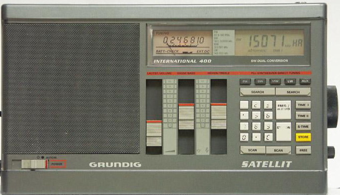
General information:
Good things:
Difficult, problematic items:
When changing the three "AA" clock and station memory batteries, leave the AC power plugged in. Otherwise, the station memory and clock times will be lost.
If possible, replace capacitors with high capacity and low voltage (470uF/6.3 or 10V, 330uF/10V, 220uF/10V) with solid electrolytic types.
In general a very good receiver, listenable in any kind of purpose: DX-ing, or just daily listening music.
Grundig Satellit 700
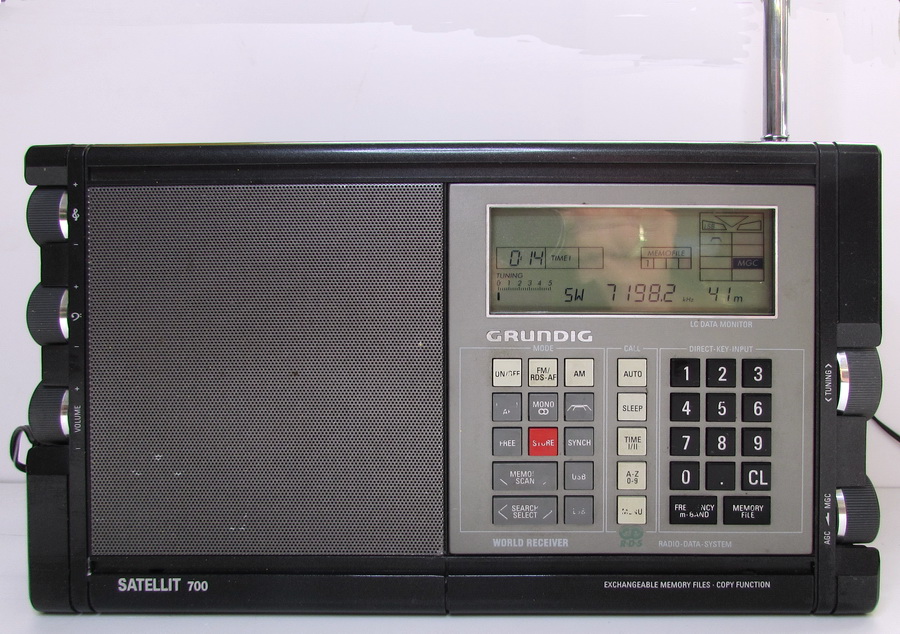
General information:
Good things:
Difficult, problematic items:
The Satellit 700 is the last "real" world band receiver from Grundig. The successor the Satellit 900 was developed and pre-production units were shown at the Funkausstellung 1995; after some friction the world band receiver production was stopped by Grundig before series production of the Satellit 900 was initiated.
Modifications: please visit https://www.condoraudio.com/wp-content/uploads/Projects/Grundig-Satellit-700-Shortwave-Radio-Repair-LED-Upgrade.pdf site, I made the same modifications.
If possible, replace capacitors with high capacity and low voltage (470uF/6.3 or 10V, 330uF/10V, 220uF/10V) with solid electrolytic types.
In general a very good receiver, very listenable in any kind of purpose: DX-ing, or just daily listening.
Grundig Yacht Boy 360
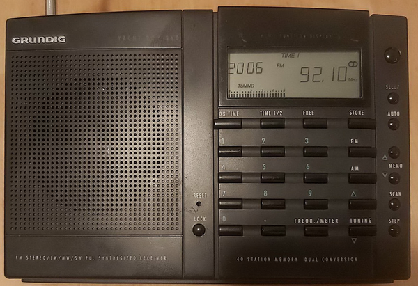
General information:
Good things:
Difficult, problematic items:
The radio's PCB is not the same as the YB400 model, the PCB is double-layer with soldered vias. The components notation on the PCB is not marked, just the polarities and perimeter of components - difficult to identify them without a detailed service manual. The technology used for soldering: glues SMD with TH components, all wave soldered.
Modifications: over 27 years, and because the used capacitors are low voltage types, their degradation level requires to be changed - but some of them were in exceptionally good condition. I used mostly solid electrolytics. The power of MPX decoder was increased from 10uF to 47uF, now both power audio output capacitors are the same, 470uF/16V, and the memory capacitor from 0.047F now is 0.22F (just, because this was what I had, and fits in place).
In general is a good radio, with very good sensibility and selectivity on FM, MW, and SW. The LW is weak. If you have the possibility, is better if you purchase the YB400, which has the SSB reception possibility, because with that you can listen the amateur bands' message. This radio is much better than the YB-P 2000!
Grundig Yacht Boy - Porsche 2000 (YB-P 2000)
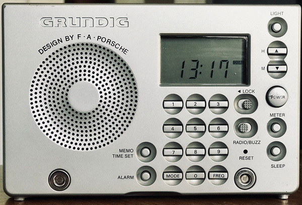
General information:
Good things:
Difficult, problematic items:
This radio has very good marketing in its time, in several magazines with high reputation was named World Receiver, but the radio part is very weak, I did not recommend regarding its low sensibility. The problem: has no any front-end circuits, which can increase its sensibility. Still, the Grundig WR5401 or the Sony ICF-SW11 is much better, which is also a single IF radio. In several radio amateur portals are highlighted this receiver's poor SW reception capability - and this is true.
Etón Co. later manufactured this radio as the Grundig G2000A, which is nearly identical to the original. Differences: the G2000A uses a different audio amplifier, the TDA22D instead of the TA7376P, and a different controller, the TC9322 instead of the TC9316F.
Modifications: over 20 years, and because the used capacitors are low voltage types, their degradation level require to be changed. I recommend solid electrolytic capacitors (or tantalum in the RF part). In position C47 instead of 470uF/10V I soldered 1000uF/6.3V OSCON type, C12 instead 22uF received 47uF, C52 was changed from 22uF to 100uF, and C51 from 100uF to 220uF, the rest of the capacitors were changed with the same values.
The keyboard rubber is fixed to PCB very ingeniously - via small rubber legs, which need to be inserted in PCB to keep their position. For reinsertion you can use component legs, pushing the wire from the opposite side of the rubber into the hole on the PCB - and for this, the legs have a cylindrical hole made for this purpose! Another thing that impressed me was the output capacitor value and is the same for both channels (usually at pocket receivers, the capacitor connected to speaker has 2x higher values than the second channel, which is used just via headphone): 470uF/10V, which gives a nice color for music via headphones for both channels.
Grundig Yacht Boy 10 - WR5401
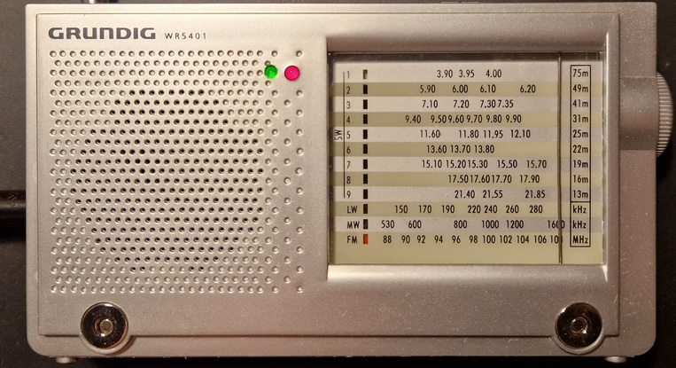
General information:
Good things:
Difficult, problematic items:
This radio is much better, then the Grundig Yacht Boy 2000.
Modification: the output capacitors value now are the same for both channels (C56, C59): 470uF/10V, which gives a nice color for music especially via headphones. The coupling capacitors between IC1 (TA2111N) and IC2 (TDA2822) were 1uF rather than the 4.7uF recommended on the TA2111N datasheet (C31, C33). Headphones now allow you to hear the entire audio spectrum, including brilliant bass and treble.
I missed the tuning indicator, which should provide an optical feedback when the radio is tuned correctly on the station. To overcome this deficiency, I connected a 560 ohm resistor and a green tiny LED to Vcc (3Vdc) and to the pin 10 of IC1 (as is in the TA2111N datasheet). The location of tuning led on the front panel is next to the stereo indication. The band selector switch is a very cheap solution: the switch soldered to the PCB does not have any positioning mechanism. The plastic band selector slider has a rack and pinion design to hold it in position by a spring with a ball pressed against it. It is questionable how much this plastic fitting will wear out with many shifts.
Always use it with the case, as the cheap painted plastic cover of the radio is very susceptible to scratches.
Overall, a very good, small portable radio with excellent sensitivity that is really enjoyable to listen to with headphones.
Harman Kardon
In the early 1950s, Sidney Harman was the general manager of the David Bogen Company, a manufacturer of public address systems at the time. Bernard Kardon was the chief engineer at Bogen. Due to management changes at Bogen in the early 1950s, both men resigned, and Sidney Harman and Bernard Kardon founded the Harman Kardon Company in 1953. By 1956, Bernard Kardon decided to retire and sold his interest in the company to Sidney Harman. As the sole head of Harman Kardon, Harman continued to make the company a technical leader in Hi-Fi products. Sidney Harman would change the company's name to Harman International, but the receivers, tuners and amplifiers were still branded Harman Kardon. The products continue to be branded as Harman Kardon to the present day. In 1969 Harman bought the major speaker manufacturer JBL. Harman Kardon's design goal is to have the highest possible design quality for the price, rather than unnecessary features. On March 11, 2017, Samsung Electronics announced the acquisition of Harman.
Harman Kardon TU-9600
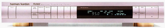
General information:
Good things:
Difficult, problematic items:
Generally: is a very good tuner for high-quality FM DX audio program listening with 2 selectable antenna inputs.
Hitachi
Hitachi is a Japanese multinational conglomerate in Chiyoda, Tokyo, Japan. Was founded in 1910 by electrical engineer Namihei Odara in Hitachi, Ibaraki Prefecture. The first products were 4kW inductor motors used in copper mining. Odaira moved headquarters to Tokyo in 1918. Odaira coined the company's toponymic name by superimposing two kanji characters: hi meaning "sun" and tachi meaning "rise". World War II had a significant impact on the company with many of its factories being destroyed by Allied bombing raids, and discord after the war. At 1958 made its first 6-transistor miniature portable radio. From 1968 start its semiconductor business with LSI hybrid ICs. 1969 color TV sets, from 1984 256kbit DRAM production, 1987 large color LCD displays, in 1990 TFT color LCD display, 1994 32bit RISC processor family and 1Gbit DRAM, 1997 4.7Gbyte DVD-RAM,...
Hitachi FT-340
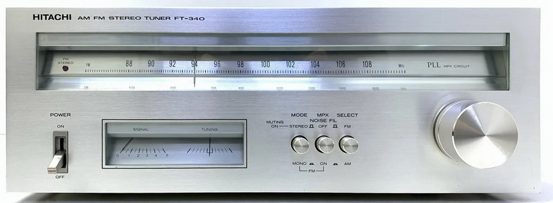
General information:
Good things:
Difficult, problematic items:
When I bought it, the tuner worked (15 Euro). The front plate was meticulously cleaned and turned out beautifully. The sound was really good; the FM scale was adjusted by 400 kHz, etc. The orange line at the top of the tuner's ceramic filters (SFE10.7MA8 -> +-280kHz, minimal loss, for high quality stereo) indicates the FM IF is 10.73MHz.
The transformer warmed up slightly after several hours of use, however the voltage regulator transistor (Q801) is quite hot. I put it on a heat sink because of this.
I increased the value of the power filtering capacitor (C803) from 330 uF to 1500 uF/35 V. The C804 is now an OSCON 270uF/16V type, while the C118 is now a tantalum type with the same capacitance. A 1000uF/35V power supply was used to replace the MPX's C308 power supply. C254 and C255 were also substituted with Oscon capacitors. Electrolytic capacitors were replaced by metallized polyester capacitors for the audio signal: the C301, C311, C312, C603L, and C603R capacitors are now all 3.3 uF/63 V, while the C601L and C601R capacitors are 1 uF/63 V. One 100uF/16V capacitor and one resistor (56 ohm rather than jumper 27) were added to the output audio buffer as power line filter (position exists on the PCB, but not marked).The bass sprang to life after this change.
It is strongly advised to replace the C1 0.033uF/250Vac Rifa PME safety film capacitor, as mine had already broken and was at risk of blowing up. This is a common issue with those old Rifa capacitors.
Hitachi FT-3500
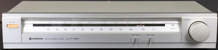
General information:
Good things:
Difficult, problematic items:
The power line received an EMI filter: 2.2nF/3kV + 2x35mH noise suppressor coil and 1uF/500V PP capacitor.
Hitachi FT-8000
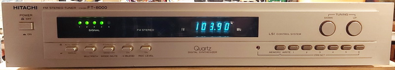
General information:
Good things:
Difficult, problematic items:
When I purchase it, the cover was with lack of paint, with bubblies, and missing tunning buttons alumina cover. After repainting and making 2 disks for buttons from outdated coins, start to look better. The front also has scratches - which cannot be removed, just cleaned. The front panel is formed from 2 plates screwed together, with glued push mechanisms for switches. The preset button forms a separate unit mounted in a plastic case cover, seems screwed, but is fixed with double side tape together and to the front panel. Inside the tuner has 3 PCBs: on the rights side close to antenna inputs is the FM front end with a shielded cover. Is interesting, that the top shield with adjusting holes is screwed, not just pressed together with the lateral shield. The other 2 big PCBs are the tuner with power supplies on the left side and the digital synthesizer with display drivers on the right side. The Q809 transistor is the most important heat generator including its heatsink.
On the net, I did not find the complete service manual, just the block diagram of the complete tuner and the analog part's schematic, with the tuner part and their PCB drawing - nothing about the digital part. This can be reconstructed from the datasheet of TC9124 controllers datasheet.
Modifications:
Just in electrolytic capacitors. All audio-signal-related coupling capacitors were changed to 22uF/50V Nichicon Fine Gold. Below 3.3uF and less were changed with foil capacitors and the rest with solid electrolytes and normal ones.
Sound: clear, smooth, and warm - this is exactly what I expected. The sonics is well balanced and not lacking in the high frequencies. Has a very analog sound, which can be listened to for a long time (that cannot be made in case of new, completely digital tuners). I think, is a very downrated tuner, which refurbished can compete with the best ones.
JVC
The Japan Victor Company, is a Japanese international professional and consumer electronics corporation based in Yokohama. Founded in 1927, the company is best known for introducing Japan's first televisions and for developing the Video Home System (VHS) video recorder. From 1953 to 2008, the Matsushita Electric Industrial Co. was the majority stockholder in JVC. In 2008, JVC merged with Kenwood Corporation to create JVC Kenwood. JVC sold their electronic products in their home market of Japan under the "Victor" name with the His Master's Voice logo, but used the name JVC or Nivico (for "Nippon Victor Company") in the past for export due to differing ownership of the His Master's Voice logo and the ownership of the "Victor" name from successors of the Victor Talking Machine Company. In 2011, the Victor brand for electronics in Japan was replaced by the global JVC brand. However, the previous "Victor" name and logo is retained by JVC Kenwood Victor Entertainment, and is used as JVC Kenwood's luxury HiFi marque.
JVC T-X1L
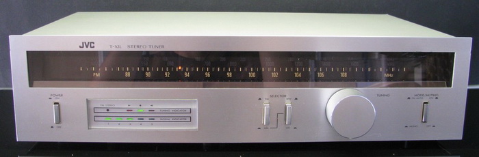
General information:
Is very interesting the scale: can be seen just the selected band ones. Consist of two transparent plexiglass with engraved scale, one for FM and one for AM (MW and LW) and are separately lighted just the used one. From the exterior can be seen just one scale, just the selected/lighted one (like on the picture).
Just some out of order electrolytic capacitors were changed in the power line.
JVC T-K10L
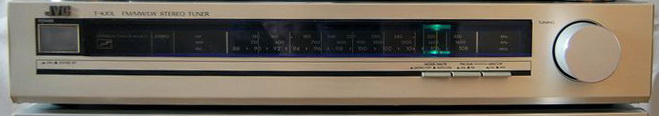
General information:
The sensibility and the stereo signal capturing outperform the specification - means at very low signal level still can receive the stereo transmission without any sizzling noise.
The scale has no backlight, just the cursor, which is made from a wide transparent plexiglass and is illuminated by bulbs separately: for AM with very light green, for FM with very light blue lights (now the miniature bulbs were changed with warm white miniature LEDs, using the colored rubber caps from miniature bulbs).
The power transformer are constantly connected to line without fuse, and the power switch connect the low voltage to tuner. During long operation the transformer remains cool. Received an EMI filter at power line input.
The RC network (10kohms in serial connection with 10uF) are not mounted on pins 4 and 5 of MPX decoder (uPC1161C3), the audio signal goes trough a low pass and band stop filter (set for 37.5kHz).
Kenwood
The company was established in 1946 as the Kasuga Radio Co. Ltd. in Komagane City, Nagano Prefecture, Japan. In 1960, the company was renamed Trio Corporation. An importer of Japanese-made electronics, A&A Trading Co for RadioShack, and a manager from there, William "Bill" Kasuga partnered with George Aratani and Yoichi Nakase decided to establish a company that would be the exclusive importer of Trio products. The name Kenwood was invented by Kasuga as being the combination of "Ken", a common name in Japan and North America that had been tested and proven acceptable to American consumers in the name of Kenmore appliances, and "Wood", referring to the durable substance as well as suggesting a relation to Hollywood, California. The brand recognition of Kenwood eventually surpassed that of Trio, and in 1986 Trio bought Kenwood and renamed itself Kenwood. George Aratani was the first chairman of Kenwood USA Corporation and succeeded by Kasuga. In October 2008, Kenwood merged with JVC to form a new holding company, named as JVC Kenwood.
Kenwood KT-815
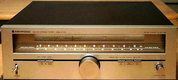
General information:
Good things:
Problematic things:
Modifications
General: all electrolytic capacitors were changed with new ones, and from below 4.7uF with foil-type (mostly WIMA), rarely with TA. Originally the power cord was for 110Vac network, I change it.
This radio on several portals is mentioned as "the KT-815 is capable of excellent RF performance but its sound quality has been criticized for being "thin" and "too dry". For that reason, mostly based on Tuner Information Center recommendation, I implement some modifications in the signal path and power supply, and the result is impressive! I highly recommend it to every owner!
Power supply (mentioned just those components, which value were changed): C15, C28, C46, C47, C49, C55, C63 47uF->100uF/63V Rubycon; C33 33uF/16V->100uF/63V Rubycon; C64 470uF/16V->1000uF/35V; C106, C107, C112, C113 1000uF/25V->2200uF/25V Rubycon; C78 220uF->1000uF/35V Rubycon; C92, C102, C103 47uF/16V->470uF/35V Nichicon; C99 33uF/16V->470uF/35V Nichicon; C108 100uF/25V->470uF/35V Nichicon; C110 100uF/10V->390uF/35V Rubycon; C23 200uF/16V->390uF/35V Rubycon. D29 RB-151 changed to 4 pcs UF4007 diodes. R170 100 ohms received in series one 2.2uH coil. In power section any high value capacitor received in parallel a 0.22-0.33uF/50V MKT. Mounted an AC filter after power cord (2.2nF/3kV + 2x7.8mH + 1uF/500V, but the 1uF was mounted after power switch).
Signal: C95, C96 10uF/16V->100uF/35V Nichicon Fine Gold; C100, C101 3.3uF/50V-> 10uF/63V MFT ROE; C104, C105 10uF/16V-> 22uF/100V MKT Vishay; C90, C91 0.22uF/50V->1uF/63V MPT; C72 270pF ceramic changed to same value PP; C77 0.047uF-> 0.47uF/50V MKT Wima; C84 received in parallel a 39pF NPO type.
Other recommended changes (not made yet): FM IF ceramic filters to be changed to low loss and narrow ones (ex. +-150kHz). Must be noted: all ceramic filters are blue dot type, which means 10.68MHz, not 10.7MHz! The output operational amplifiers is recommended to be changed with modern low noise types (MC34081, OPA2604, OPA2132 or AD845 are recommended, and can be tested other types), but a SIP8 to DIP8 adaptor is required (I made myself). Is also recommended to be changed the power line path, or take out the balun transformers at the FM antenna input (this can increase the sensibility with +3dB), or take out the FL6 and FL7 filters from the audio output.
In general, is a remarkably good tuner with a lot of upgrade possibilities!
Kenwood KT-80
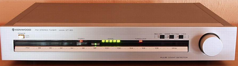
General information:
Good things:
Difficult, problematic items:
In some forums are mentioned changes to improve the sound shortening its path on the PCB or components: taking out the calibration tone generator, and the signal can go from C40 to C33 using one capacitor, or taking out the R39-R40, C51-C52 (bypassing the last 2), etc.
Modifications:
All electrolytic capacitors changed. Below 4.7uF anywhere, and below 10uF in the signal path with foil capacitors. In the next will be mentioned were I changed or added new components.
Power path: C13, C57, C66 were replaced with 100uF/63V Nichicon, C83 with 2200uF/25V Rubycon, C63, C86 and C88 all replaced with 390uF/35V Rubycon, C27 and C74 replaced with 1000uF/35V Rubycon. Jumper J9 was replaced with a 220ohms resistor (is the power line of IC3/AN610), and in parallel with C16 was mounted a 270uF/16V OSCON with 100pF. On power transformer primer coil after power switch received in parallel one 470nF/275Vac pp, and on secondary, on both outputs one-one 470nF/275Vac pp foil capacitors.
Signal path: C22, C29 and C31 instead of 0.047uF all were replaced with 1uF/63V pp, C35 changed to 47nF/100V pp, C34 received in parallel 47pF C0G MLCC, between pin 5-6 of HA12016 one 100pF C0G. R18 changed from 1.8kohms to 1kohms. In parallel with C38 on pin 12 of HA12016 inserted one 10nF C0G, same with C61 on pin 13 of HA1137W received 10nF C0G. C39 replaced with 2.2uF/63V pp. C41 and C42 were replaced with the same value, 47uF/63V Nichicon Fine Gold type. R39-R40 changed from 3.3kohms to 5.6kohms. Basis of changes - Kenwood KT-L01T model.
The VCO of HA12016 is difficult to adjust, can be measured the 76kHz signal just between VR1 and R28. After changing all electrolytes needs to be readjusted.
On the PCB of the tuner, around HA12016 can be found the positions of components for 75us de-emphasis, but are omitted including with de-emphasis selection switch in my European version. The most often linked service manual on the net has an error: the output audio signal comes from the negative input of the output buffer amplifier of IC5/HA12016, but correctly comes out from the real output - pins 4 and 7.
Upgrade: (idea implemented from KT-615) at the gate of Q1 R1 instead of direct ground connection is better to be connected to ground via 10kohms, and this point to be connected to the power supply via one 470kohms resistor. This will increase a bit the sensibility of the tuner.
With improved capacitors in the signal path, improved power lines and all other modifications result is a detailed and clear sound.
Kenwood Basic T2
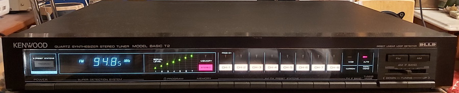
In Japan was sold as Kenwood KT-1010 II or under the brand name Trio KT-1010.
General information:
Good things:
Difficult, problematic items:
The frequency display is shifted with 50kHz, I did not find how can be adjusted correctly, but with this deviation, the signal is on max value, the stereo decoder works correctly. At AM the sensibility is exceptional: I have never seen such sensibility with the loop antenna, no ferrite bar inside.
The original price was 798DM at 1984.
Modifications:
Basically, because is a well-made tuner, just the power line can be improved. Compared to all datasheets of used ICs, just one significant item I found: the pin 18 of uPC1223 stereo decoder is decoupled with 820pF to the ground.
Modification of power lines: C27, C95 1000uF/35V; C60, C85, C91, C113, C151, C154, C177, C184 390uF/35V; C73, C89, C95, C110, C119, C161, C163, C169, C173 100uF/63V; C146 2200uF/25V; C159 560uF/35V. Additionally was inserted coils in power lines, to decrease the noise between units: in tuner section, J145 jumper was replaced with 10uH/0.2 ohm coil; in IF demodulator section, with R54 in series was inserted 22uH/0.3 ohm coil; in stereo demodulator section, J68 was replaced with 47uH/0.6 ohm; in the power circuit of PLL controller J172 jumper was replaced with 10uH/0.2 ohm.
Kenwood KT-880DL
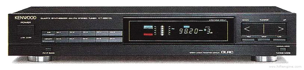
General information:
Good things:
Difficult, problematic items:
Modification (based on FM TunerInfo, posted by JohnC, modified to my components):
Old electrolytics were ELNA type in average shape: some of them were OK (50% of 10uF/35V), but those with high capacitance and low voltage, like 100uF/10V or 220uF/6.3V were in poor condition. All were changed.
Power line: C137 changed to 4700uF/25V; C138 and C150 to 680uF/50V; C142, C151, C152 to 1000uF/35V; C32, C51, C65, C108, C120, C132, C133, C135, C148, C165, C181, C194 to 100uF/63V; C54 to 390uF/35V; C193 to 3300uF/16V; C128 to 22uF/50V. At AC power input received an EMI filter circuit formed by 2.2nF/2kV ceramic capacitor, a 2x6.7mH filter coil, and after in parallel with the primer coil of transformer one 0.68uF/275Vac pp foil capacitor.
Audio output: all capacitors were changed with polypropylene type. Instead of 10uF I use 2 pcs of 4.7uF in parallel. Capacitors changed: C54, C60, C64, C78, C79, C82, C83.
All other electrolytics below 4.7uF changed to foil type.
Other recommended modifications: rectifier diodes to be changed into Schottky type, and insert an operational amplifier as audio buffer on output after LA3401 filters, like in KT5020 model.
Now has good stable image, wide soundstage, midrange is pretty good, nice tight bass and fairly deep, and the treble is clear.
Kenwood KT-5020L
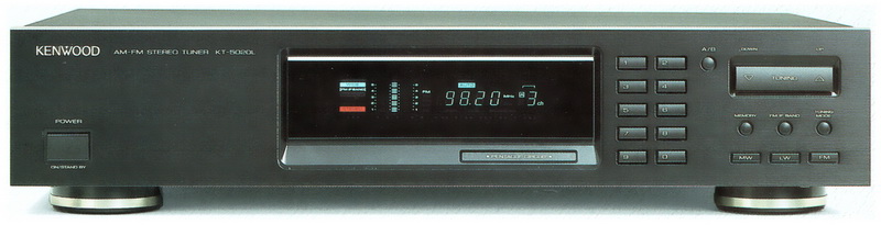
Other family members: KT-1020L, KT-2020L and KT-7020.
It is ranked as 7th best tuner, as sensibility and audio quality. Interesting: the top Kenwood (and other) tuners, like KT-990D, L-1000T, KT-917, KT-1100, KT-3300D, KT-8300, Pioneer F-90 and Onkyo T-9090II and KT-7020 are behind this, exactly in this order. (contest published by fmtunerinfo.com, shouts #68 to 81 from 20 Apr 2004 till 12 Dec 2006, comparison made with 84 tuners)
General information:
Good things:
Difficult, problematic items:
Modification (based on FM TunerInfo, posted by Jim, modified to my components):
All electrolyte capacitors were ELNA type, which at that time were good, but their degradation is fast. I measured all of them, and some of them have high ESR (above 6 ohms), high loss (higher than 20%). For this reason, I changed all of them (with pp below 4.7uF and solid electrolyte types, exception just above 330uF).
In the audio part, all 7 pcs of 10uF/35V Elna (C90, C101, C102, C107, C108, C111 and C112) were changed into 10uF/50V bipolar Nichicon Fine Gold capacitors.
Received a power line filter: 2x1uF/275Vac, 2x12mH noise-canceling coil, and one 2.2nF/2kV ceramic capacitor.
Now has a good stable image, wide soundstage, the midrange is pretty good, nice tight bass and fairly deep, and the treble is clear.
Other recommended modifications (not made yet): rectifier diodes to be changed into Schottky type, change the actual audio buffer, mount a socket, and insert a better OPA, like OPA2132.
Kenwood KT-1050L
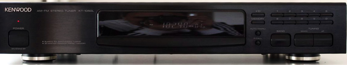
General information:
Good things:
Difficult, problematic items:
As usual, was necessary to change all electrolytic capacitors. In RF parts received tantalum type capacitors, in other areas, below 4.7uF film capacitors, in audio part Nichicon Fine Gold, in the power line, above 22uF Nichicon or Rubycon capacitors.
Luxman
Lux Corporation was founded in Japan in June 1925, by T. Hayakawa and his brother K. Yoshikawa. The company began as the radio equipment department of Kinsuido Picture Frame Store in Osaka, until then only an importer of picture frames, and was founded just ahead of the first radio broadcast that year.
At the time, Japanese radio listeners were dependent on technology originating in the United States and Europe. Importing radio equipment and parts was a very forward-looking enterprise for Lux, and passersby often crowded the store to hear the inviting sounds of the radios on display. Lux Corporation later decided that to compete effectively as a supplier, it had to not only sell equipment but manufacture parts in-house to reduce the costs of importing, beginning the creation of the Luxman brand. As a result of this pursuit, Luxman became famous for the output of various quality transformers and switches in Japan, and today is one of the oldest manufacturers in Japan of electronic components, which is reflected in the company's tagline "Ultimate Fidelity since 1925". In the mid-1970s and early 1980s, Luxman rose to prominence in the world hi-fi community, owed to the quality sound produced by its equipment. Luxman was primarily a specialist in making vacuum tube amplifiers of the highest caliber. One of the traits of Luxman equipment from this era is the quality and warmth of vacuum tube sound, paired with powerful solid-state electronics and often beautiful, minimalist aesthetic designs.
An engineer by the name of Atsushi Miura married Mari Yoshikawa (Mr. K. Yoshikawa's eldest daughter) and became a part of the founding 'Luxman' family. Atsushi Miura's father was an audio engineer and was head of Luxman for many years in Japan. In the early 1980s, Atsushi took over the reins from his father to run Luxman. Sensing the Japanese audio industry was heading towards cheaper mass-produced components and against the founding philosophy of Luxman, Atsushi sold Luxman to Alpine in 1984, before starting the Airtight audio brand. Alpine, wishing to merge their home hi-fi divisions and Alpine brand with Luxman gear, took corporate actions which nearly bankrupted Luxman. The first of these corporate mistakes was getting Luxman involved in a hi-fi market share war with rival consumer electronics brand Yamaha. Up to the point of the merge, Luxman was revered as a prestigious audio brand; one that sold its equipment in specialist independent hi-fi shops. Post-merge, Luxman looked to sell their products to companies such as Costco (United States) and Richer Sounds (UK) to compete with Yamaha. This plan resulted in much confusion amongst consumers, as well as their perception of the brand's values. Where Luxman's reputation was in high-end and often expensive markets, its new distributors had reputations for selling in budget and low-value markets, causing problems for existing dealers and consumers loyal to Luxman's values. The second corporate mistake by Alpine was problems with product branding and poor product planning. While Alpine equipment was seen as "okay" and "acceptable" in most consumers' eyes, Luxman was seen as a perfectionist and even elitist brand. The co-branding of cheap and inferior plastic Alpine products with expensive Luxman gear (Luxman equipment was badged Alpine/Luxman) in both Alpine and Luxman factories caused further confusion amongst consumers. This move totally destroyed the image and, ultimately, the sales of Luxman equipment, and the company ended up retreating from all its sales network worldwide except Japan.
Alpine, due to all the troubles it experienced with the Luxman brand, sold it off in 1994. In 2009, Luxman Corporation was acquired by the International Audio Group Ltd. IAG.
Luxman T-4
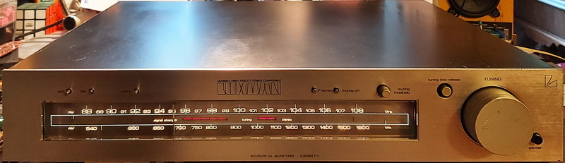
General information:
Good things:
Problematic things:
The oil-paper capacitors from the main switch were cracked, and the epoxy cover starts to peel off. Both were replaced with 2.2nF/3kV ceramic disk capacitors.
Power section: C103 and C168 now is 100uF/25V solid electrolyte capacitor (was necessary to decrease the value of R202 from 47k to 15k), C175 now is 3300uF/25V, C176 is 2200uF/25V, C147, C169, C172, C173, C216, C311, C312, C313 now are 470uF/35V, C163 is 10uF/35V.
In signal path C158 and C159 now are 3.3uF/100V pp, C161 and C162 now are 0.47uF/63V pp, rest below 4.7uF all pp.
Marantz
Marantz is a company that develops and sells high-end audio products. The company was founded in New York, but is now based in Japan. The first Marantz audio product was designed and built by Saul Marantz in his home in Kew Gardens, New York. The company had a major influence in the development of high-fidelity audio systems, and reached the high point of their success in the mid to late 1970s. During the 1980s, while owned by Philips, a pioneer in compact disc technology, Marantz sold some very well received CD players, but other products in the line were not as successful as in the past. Beginning in the early 1990s, Marantz focused on higher-end components. In 2001, Marantz Japan acquired the brand from Philips and owned all overseas sales subsidiaries. 2002 merged Marantz with competitor Denon into D&M Holdings Inc., later named in D+M Group. On March 1, 2017, Sound United LLC completed the acquisition of D+M Holdings.
Marantz ST 450
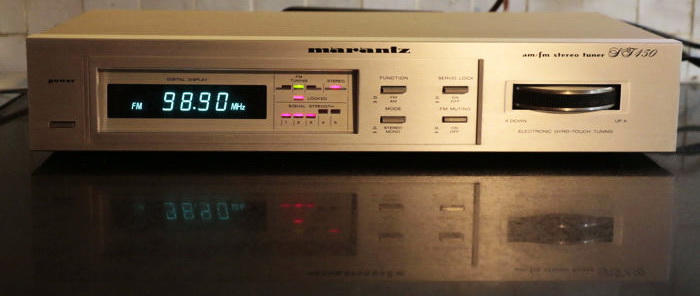
General information:
Good things:
Difficult, problematic items:
Marantz ST 530
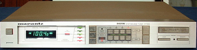
General information:
Good things:
Difficult, problematic items:
Marantz ST-64L
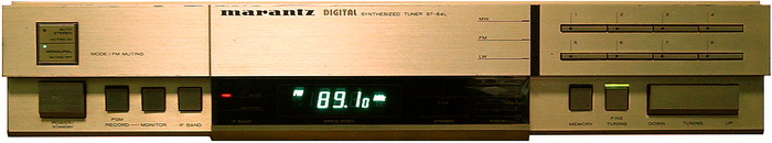
General information:
Good things:
Difficult, problematic items:
Marantz ST-6000
General information:
Good things:
Difficult, problematic items:
Several forums mention this tuner as a well-regarded option, recommending various modifications. These include not only increasing the values of certain capacitors or replacing them with higher-grade alternatives, but also switching to Schottky type rectifier diodes. Additionally, suggestions involve changing the operational amplifier at the output (the audio buffer is a Fairchild KA4558s SIP-9 IC), modifying the audio feedback network, and, in my view, relocating the voltage regulator ICs to the back of the chassis to dissipate heat more effectively or replacing them with a less noisy LM317 regulator along with some extra components. Even without a bottom plate in the steel chassis, removing the board is quite straightforward due to the connectors utilized.
Overall, it is an effective tuner, particularly when the signal is sufficiently strong - the sound is rich with warm bass. It exhibits a somewhat loudness-like response, emphasizing the bass slightly more than the treble. However, this could equally be attributed to a very linear low range and a slightly subdued high range, potentially due to the necessity of filtering out the pilot tone. Nonetheless, this sound is quite enjoyable, possessing a touch more warmth than necessary.
I did not recommend it for DX or for the countryside, where some stations have a low signal level. However, if you reside in a well-covered area, this tuner delivers magnificent sound!
NAD
The NAD Electronics (NAD Electronics) company was founded in London, England, in 1972 by Dr. Martin L. Borish, an electrical engineer with a PhD in physics. Its most famous product is the late-1970s NAD 3020, an integrated amplifier designed by Bjørn Erik Edvardsen, which was highly regarded by various magazines in Britain. NAD's philosophy is to include only genuinely useful features for aesthetically understated designs when compared to other competitors' products. NAD was one of the first audio manufacturers to outsource the manufacturing of its products to electronics factories in east Asia. NAD was acquired by the Danish firm AudioNord in 1991 and subsequently sold in 1999 to the Lenbrook Group of Pickering, Ontario, Canada.
NAD 4220
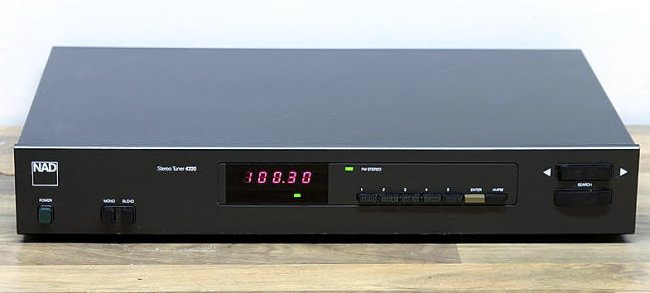
General information:
Good things:
Difficult, problematic items:
Modifications:
Power: both heat generators (Q501 and Q502) were mounted on the internal stiffener plate. Is still made from iron, and is situated in the radio, but the heat now was taken out from the neat of the capacitors
The power line input received an EMI filter, and related filtering capacitors were changed and/or increased their values. C510 390uF/35V, C515 and C519 330uF/50V, C516 and C522 100uF/63V, C518 and C520 47uF/35V solid electrolyte. C143 received in parallel a 100uF/16V and C117 replace with 100uF/16V, both solid electrolyte capacitors. C904 received in parallel an additional ceramic capacitor, 4.7uF/35V.
This tuner has a musicality, very listenable - but different from Marantz or Technics. Like a tuner with a clear character, a different identity. Its sensibility is just average, not recommended for DX.
Nikko
Nikko Audio was a division of the Japanese electronics company Nikko Electric Industry Co, which was formed in 1933 in Kanagawa. The original ,Nikko Electric Works' was re-founded shortly after WW2 in 1948 as a designer, manufacturer and installer of communication technology and electrical equipment in Japan. In those early years, Nikko mostly manufactured fuses for the Japanese National Railroad - until the daughter of the boss married a young audiophile lad who allegedly had "golden ears" and persuaded his father-in-law to put on a range of HiFi products, a process that began in the late 1960s. The son-in-law understood about good sound, but he was only marginally interested in the marketing of his products, so that he initially developed devices that were very good, but also very expensive and therefore difficult to sell. With the Audio Division hardly generating enough income for itself in the 1970s, Nikko was forced to revise its strategy and spin off into various foreign subsidiaries. The product range was streamlined and most of the early High End gear was removed in favor of less expensive and therefore more marketable equipment. Although the product quality was easily able to keep up with the competition, they did not perform in terms of sales, which was mainly due to their overly conservative appearance. In contrast to Sony or other big names with their brushed aluminium fronts, Nikko designers could not (or did not want to) follow this trend and therefore had a hard time holding their own in the market. A later reorganization of the product range saw the launch of compact equipment in the lower and medium price range. Nikko also entered the German market with these products, among others; they were introduced via various importers and then sold preferably via department store chains or mail order (i.e. the low-cost segment). Soon, a name and products that were still relatively unknown but that had been poised for greatness sold out to the market and the company finally closed business following the general market slump after the Asian flu at the end of the 90s (In 1999 the company was taken over by a investment company controlled by the Rotchild's).
Nikko STA7070
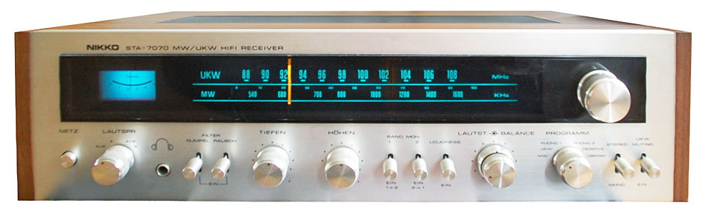
General information:
Good things:
Difficult, problematic items:
The front view is lovely. Everything has been done honestly. Repairs, even replacing parts, are simple for radios and preamplifier part, but tone board and power amplifiers are a nightmare due to their inaccessibility. To gain access, I had to unscrew everything (the connections between the panels were fixed by wrapping). The switches are encircled by a web of wires, making them nearly unreachable. At the time, the modular system had already appeared, but they were built in, with the wires catted to size after installation, of course, well wrapped, threaded through, and then soldered together to prevent them from being destroyed by a nuclear explosion or an earthquake.
I obtained it in functioning order, therefore the primary task was to refurbish it. The old electrolytic capacitors worked properly; they were Marconi type and were 50 years old. Their condition is generally satisfactory; their capacitance has increased significantly, but their losses remain moderate.
Modifications/upgrades:
Nikko products are sometimes underpriced because they are not well-known, and their design is not as impressive as Marantz's, but their sound and construction are on par - in my opinion.
Nokia
Nokia Corporation (natively Nokia Oyj in Finnish, referred to as Nokia) is a Finnish multinational telecommunications, information technology, and consumer electronics corporation, established in 1865, when Finnish-Swede mining engineer Fredrik Idestam established a pulp mill on the shores of the Tammerkoski rapids near the town of Tampere, Finland. In 1922, in a now independent Finland, Nokia Ab entered into a partnership with Finnish Rubber Works and Kaapelitehdas (the Cable Factory). The rubber company grew rapidly when it moved to the Nokia region in the 1930s to take advantage of the electricity supply, and the cable company soon did too. In 1967, the three companies - Nokia, Kaapelitehdas, and Finnish Rubber Works - merged to create a new Nokia Corporation, restructured into four major businesses: forestry, cable, rubber, and electronics. In the early 1970s, it entered the networking and radio industries. Nokia started making military equipment for Finland's defense forces. In 1977, Kari Kairamo became CEO and transformed the company's businesses. By this time, Finland was becoming what has been called "Nordic Japan". Under his leadership, Nokia acquired many companies, including television maker Salora in 1984, followed by Swedish electronics and computer maker Luxor AB in 1985, and French television maker Oceanic in 1987. This made Nokia the third-largest television manufacturer of Europe (behind Philips and Thomson). In 1987, Nokia acquired Schaub-Lorenz, the consumer operations of Germany's Standard Elektrik Lorenz (SEL), which included its "Schaub-Lorenz" and "Graetz" brands. It was originally part of American conglomerate International Telephone & Telegraph (ITT), and after the acquisition products were sold under the "ITT Nokia" brand, despite SEL's sale to Compagnie Générale d'Electricité (CGE), the predecessor of Alcatel, in 1986. After 1990 started the computer, mobile and network business with a deep restructuring of company profile. On 12 June 1996, Nokia announced the sale of its television business to Canada/Hong Kong-based Semi-Tech Corporation. The television manufacturing plant in Germany closed down in September 1996. The sale included a factory in Turku, and the rights to use the Nokia, Finlux, Luxor, Salora, Schaub-Lorenz and Oceanic brands until the end of 1999. Some of these brands were later sold to other companies.
Nokia RP-9160
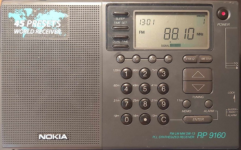
General information:
-
Shortwave bands - can be selected also by meters/wave length, and any frequency can be selected also between bands:
Good things:
Difficult, problematic items:
Nordmende
Nordmende comes from Norddeutsche Mende-Rundfunk GmbH, a radio company founded in 1923 by Otto Hermann Mende in Dresden, and was rebuilt after WWII in Bremen in 1947. In the 1980s, the factories in Bremen were closed, Nordmende becoming purely a Thomson trademark (sold by family). This means this radio was made in the transition era, but Nordmende already was a Thomson affiliate.
Nordmende TU-1300
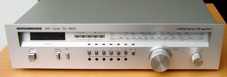
General information:
Good things:
Difficult, problematic items:
Onkyo
Onkyo Corporation is a Japanese consumer electronics manufacturer, specializing in premium home cinema, and audio equipment, including AV receivers, surround sound speakers and portable devices. The company started under the name of Osaka Denki Onkyo K.K in 1946. The word Onkyo translates as "sound resonance". The current Onkyo Corporation umbrella includes the Integra and Integra Research divisions as well as the main Onkyo brand. In March 2015, Onkyo purchased Pioneer Corporation's Home Electronics Corporation. In return, Pioneer took a 14.95% stake in Onkyo.
Onkyo TX-2500
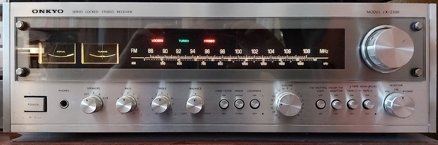
General information:
Good things:
Difficult, problematic items:
The radio part has 2 versions: NAIMX-345, a simpler, and NAIMS-345, a more complex one (S means Super?), this last one is a better version, seems more similar with MKII (looks like a transition between them). I have the version NAIMX-345, but on the PCB can be seen position of components from NAIMS-345, but not all of them. Ex. position of T102 was shunted, and I replaced with the right C-L components, or in L101 position was mounted a 100ohms resistor (like in MKII), I replaced it with 3.3uH inductor.
Its sensibility outperforms some tuners with better specifications.
The TX-2500 on AM are with 2 gangs, on FM are with a 3-gangs variable capacitor, two IF amp stages, 2 pcs of 10.7MHz ceramic filters, and an Onkyo-made low-pass filter (NMC-8-7). Recommended to be improved: the audio stage separation from common radio power with a 56 ohms resistor followed by a puffer capacitor 470uF/25V. In the RIAA feedback network, is recommended to be changed the C304/C404 from 3.9nF to 3.6nF+220pF - but to be identical, PP capacitors from same type and same manufacturer. I added 1-1 uF/100V in parallel with C905/C906 4700uF/80V Nichicon capacitors in main power supply.
Onkyo T-3100
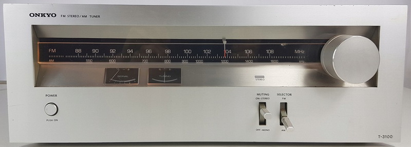
General information:
Good things:
Modifications: excepting output buffer, all improvements from T-5000 were built into this tuner, and received an EMI filter at power AC input. The scale lighting was changed to LEDs (4 warm light LEDs/side), and also the stereo bulb now is a red LED.
Onkyo T-9060
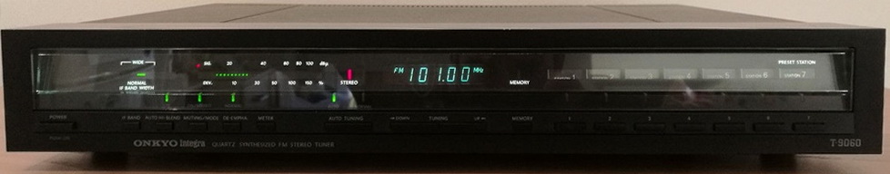
General information:
Good things:
Modifications
Because the transformer was noisy, I added a 3mm thick rubber under it. Now is perfectly silent. The 7812 regulators - which produces a lot of heat (the power line voltage is 240V instead of 220V) - was installed on the backside plate. All electrolytics with 6.3V nominal voltage (usually 100uF, 330uF, and 1000uF) were out of order, I recommend to be changed to solid electrolyte type. Audio signal path capacitors changed to Elna bipolar 47uF. The sound is really nice and detailed, especially when the output capacitors were changed. Because the NJM4558 is not a high-end model, I recommend replacing the opa with a better one.
Onkyo T-4210R
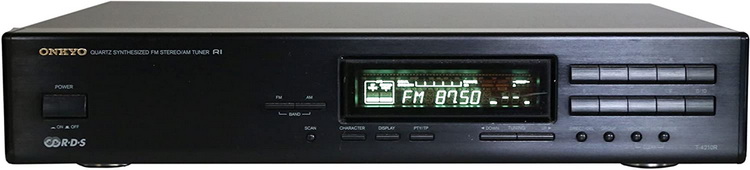
General information:
Good things:
Modifications
All modifications covers the power lines, noise reduction and sound improvements. On Power line: C002 100uF/16V replaced with 390uF/35V, C114 22uF/16 replaced with 100uF/63V, C205 470uF/16V replaced with 1000uF/35V, C220 47uF/16V replaced with 100uF/63V, C706 220uF/6.3V replaced with 390uF/35V, power cap of RDS 10uF/16V replaced with 100uF/63V, C902 2200uF/25V with 3300uF/25V, C904 470uF/16V replaced with 1000uF/35V, C905 10uF/50V with 100uF/63V, C907 47uF/16V with 100uF/63V, C913 47uF with 100uF/63V, C914 220uF/35V with 390uF/35V, C915 220uF/35V with 390uF/35V, C919&C920 with 390uF/35V. Received an AC power line filter: 2.2nF/2kV, 2x7.8mH and 0.68uF/275Vac.
Other changes: C117 1uF/50V to 3.3uF/100V PP, C169 10uF/35V to 4.7uF/63V PP, jumper J109 replaced with 3.3uH coil, C202 22uF/16V with 4.7uF/63 PP (based on input impedance was not justified to increase above 4.7uF), C211&C212 22uF/16V with 10uF/63V PP (that can be increased, depends by the input impedance of preamplifier. The best solution should be a separate buffer on the end of MPX decoder).
Onkyo T-4970
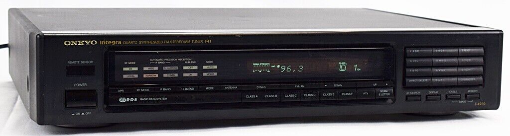
General information:
Good things:
Onkyo T-4211
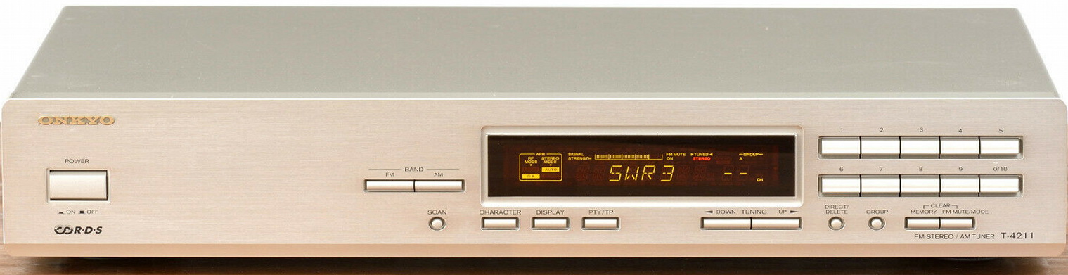
General information:
Good things:
Modifications
All modifications covers the power lines, noise reduction and sound improvements. On Power line: all capacitors changes, for tuner, RDS and IF with solid electrolyte capacitors. Tuner supplying go through a ferrite bear. Received an AC power line filter: 2.2nF/2kV, 2x5.9mH and 0.47uF/275Vac.
In audio path: the MPX input and the audio outputs received 47uF/25V ELNA bipolar capacitors. The best solution should be a separate buffer on the end of MPX decoder). This increased the lower range of output, now seems more equilibrated the whole audio.
Panasonic
Panasonic Corporation, (Panasoniku kabushiki gaisha) formerly Matsushita Electric Industrial Co., Ltd. is a major Japanese multinational electronics company, headquartered in Kadoma, Osaka. It was founded by Konosuke Matsushita in 1918 as a lightbulb socket manufacturer. In 1927, Matsushita adopted the brand name "National" for a new lamp product. In 1955, the company began branding audio speakers and lamps for markets outside Japan as "PanaSonic", which was the first time it used the "Panasonic" brand name. The company began to use the brand name "Technics" in 1965 for high fidelity audio equipment. Throughout the 1970s and early 1980s, Matsushita continued to produce high-quality specialized electronics for niche markets, such as shortwave radios, and developed its successful line of stereo receivers, CD players, and other components. The use of multiple brands lasted for some decades. While 'National' had been the premier brand on most Matsushita products, including audio and video, 'National' and 'Panasonic' were combined in 1988 as National Panasonic after the worldwide success of the Panasonic name.
Matsushita's brother-in-law, Toshio Iue, founded Sanyo as a subcontractor for components after World War II. Sanyo grew to become a competitor to Matsushita but was later acquired by Panasonic in December 2009.
Since that time, Panasonic closes its plasma (2011) and LCD (2021) displays manufacturing, solar panels (2021), and semiconductors (2019) manufacturing business.
Panasonic RF-9L
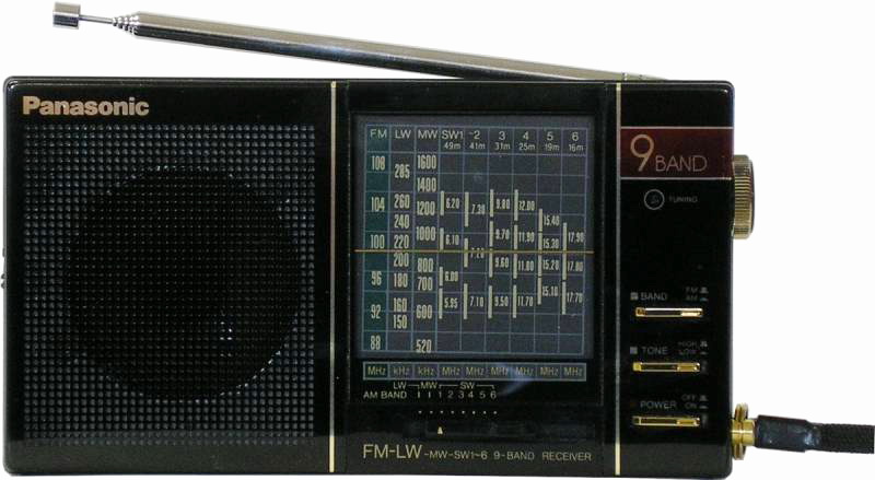
General information:
-
Shortwave bands:
Good things:
Problems:
Panasonic RF-B20L
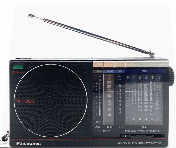
General information:
-
Shortwave bands:
Good things:
Problems:
Deviation in original set compared to service manual: instead of C71 an C72, both should be 470uF/6.3V, was mounted just in C72 position one capacitor with 1000uF/6.3V. C69, instead of 1000uF/6.3V was mounted 470uF/6.3V, and C64 on schematics should be 22uF/50V, in the set was mounted 2.2uF/50V.
Changes and modifications: C69 was changed back to 1000uF/6V, C64 now is 3.3uF/50V, C71 and C72 changed back to 2 pcs of 470uF/6.3V dry electrolyte capacitors, C54 instead of 220uF/6.3V now is 270uF/6.3V dry electrolyte type. All other capacitors changes with dry electrolyte, excepting 2 pcs of 47uF/6.3, now they are tantalum type. The highest effect has the audio output capacitor - is not an audio grade, but the sound has more bass (taking in consideration the size of the speaker and the old capacitor).
The RF-B20 makes a decent travel companion if you can live without 22m coverage.
Panasonic RF-B45
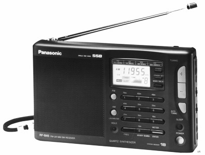
General information:
-
Shortwave bands - can be selected also by meters/wave length:
Good things:
Problems:
Recommendation: I changed the CFX3 and CFX2 10.7Mhz (Murata type with 280kHz BW and 6-7dB loss) ceramic filters with a Murata 150kHz BW, 4-5 dB loss filters. Sensitivity lightly increased on FM, and no adjacent programs can be heard, and easily can be found the real transmission frequency of FM radio station.
The sound is very clear, especially on midrange and treble, but with less bass. This can be improved by changing the output capacitor from 220uF/6.3V to 470uF/6.3 solid electrolyte type.
Next step for improvement: to change the headphone jack into a stereo one, and to move the power button LED to backlight the LCD (more useful).
Panasonic GX-500 (RF-3500)
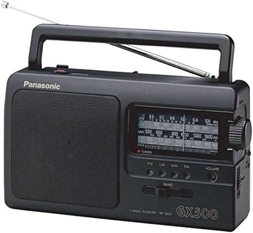
General information:
Good things:
Problems:
To have a smoothe AM radio listening, I mounted after rectification an EMI filter formed by 1uF+2x20mH+1uF, on primer side of transformer one 2.2nF ceramic capacitor in paralel, and on secondary side 0.1uF ceramic capacitor. The filering capacitor were increased to 2200uF/10V.
Panasonic RF-U350
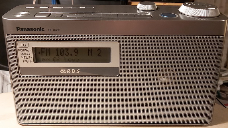
General information:
Good things:
Problems:
Recommendation: I replaced every electrolytic. Every variety of 6.3V was in bad shape.
CGiven all of the hardware that has been included in this radio, it is unclear why Panasonic has not taken advantage of its options, such as switchable backlighting for the display, clock auto setting from RDS, and stereo listening through headphones.
With its full range 10cm speaker, the sound is crystal clear. A radio is a great option for everyday use in the workplace or in the kitchen. Its sound did not appeal to me personally. is not a smooth radio or one that can be listened to for a long time. Although it's hard to put into words, I get the impression that it sounds rather lifeless and extremely digital.
Philips
The Philips Company was founded in 1891, by Gerard Philips and his father Frederik Philips. Frederik, a banker based in Zaltbommel, financed the purchase and setup of an empty factory building in Eindhoven, where the company started the production of carbon-filament lamps and other electro-technical products in 1892. In the 1920s, the company started to manufacture other products, such as vacuum tubes. In 1927, Philips began producing radios.
In 1980, Dutch Philips Group bought the Marantz (in 2001 Marantz Japan acquired the brand back from Philips), and in 1984 bought out nearly a one-third share and took over the management of German company Grundig.
On 29 January 2013, it was announced that Philips had agreed to sell its audio and video operations to the Japan-based Funai Electric.
Philips L1W35T
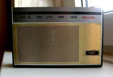
General information:
Philips FT920

General information:
Philips FT930
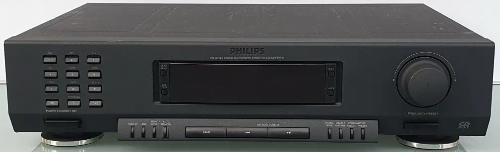
General information:
Good things:
Difficult, problematic items:
Philips FT980
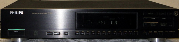
General information:
Good things:
Difficult, problematic items:
Generally: is a very good tuner with high sensibility and selectivity for FM DX audio program listening.
As usual for its age, was necessary to change all electrolytic capacitors. In RF parts received tantalum type capacitors, in other areas, below 4.7uF film capacitors, in audio part Nichicon Fine Gold, in the power line, above 22uF Nichicon or Rubycon capacitors.
On some portals are recommended to be changed the C311 adjustable capacitor with a teflon type, but in my one, I did not see any reason to change it. After comparing the schematics and specifications of the above-mentioned tuners, I decided to upgrade the tuner with component values used in Grundig Fine Arts T4 and/or Marantz ST72, changing R105 4.7k into 3.6k, R145 10 ohm into 4.7 ohms, R187 10k into 6.8k, R315 120k into 56k, and insert a 3.3uH (L11) coil in the power line of FM-IF operational amplifier. To my surprise, those were originally changed/inserted by manufacturer -> means the Philips FT980 RF parts differ from its service manual and are same with the RF parts used in Grundig Fine Arts T4. Marantz ST72 has additionally other values in the case of some components, like in FM oscillator or in FM tuner output amplifier, but I considered risky their changes regarding surrounded RF circuits.
List of other differences between Philips FT980 and Marantz ST72L: R16 8.2k/100, R165 1.2k/1k, R181 47/220, R301 31/390, R309 330/68k, R311 220k/68k, R322 3.9k/5.6k, C112 10n/47n, C113 10u/no, C145 4.7n/390p, L11 no/3.3u. The RF coils cannot be compared, because in both manuals has a different notation (looks like Philips and Marantz used a different notation system), but their position-number, appearance, and the capacitors from the circuit are the same.
Pioneer
Pioneer Corporation (Paionia Kabushiki-gaisha) commonly referred to as Pioneer, is a Japanese multinational corporation based in Tokyo, Japan, that specializes in digital entertainment products. In 1937: Pioneer's founder, Nozomu Matsumoto develops the A-8 dynamic speaker, and one year later, in 1938 Fukuin Shokai Denki Seisakusho (precursor of Pioneer) is founded in Tokyo as a radio and speaker repair shop. In May 1947 Fukuin Denki is incorporated, and in June 1961 company name changed to Pioneer Electronic Corporation. Pioneer played a role in the development of interactive cable TV, the Laser Disc player, the first automotive Compact Disc player, the first detachable face car stereo, Supertuner technology, DVD and DVD recording, the first AV receiver with Dolby Digital, plasma display and Organic LED display (OLED). In March 2010, Pioneer stopped producing televisions as announced on 12 February 2009. On June 25, 2009, Sharp Corporation agreed to form a joint venture on their optical business to be called Pioneer Digital Design and Manufacturing Corporation. In September 2014, Pioneer agreed to sell Pioneer Home Electronics (Home A/V) to Onkyo. In June 2021, Voxx International announced that it had finalized a licensing agreement with the Pioneer and Pioneer Elite brands "for all markets, except China" as part of their acquisition of Onkyo.
Pioneer F-90
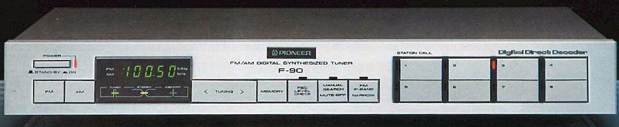
General information:
Good things:
Difficult, problematic items:
The tuner is very similar to the latest and famous F99X model, excepting the 2 IF amplifier stages, separate for Wide and Narrow IF circuits, for better selectivity. The F90 is a simple but good-sounding tuner, and can be asked, how this tuner gets this sensational data of 0.01% (mono) or 0.02% (stereo) distortion; a crosstalk attenuation of 65dB; and a massive 93dB signal-to-noise ratio (mono) and 85dB selectivity (400kHz, narrow IF)? The answer is simple: via the 2nd IF stage and its patented DDD (Digital Direct Decoder) which uses two proprietary ICs (PLL muting PA5007, and a DDD with pulse-count detector PA5006). The IF signal with its maximum frequency deviation is doubled via Q110 and Q111 to get the 21.4 MHz with maximum frequency deviation +-150kHz - and this is mixed with the second local oscillator (20.14MHz) to get the 2nd IF signal of 1.26 MHz (Q305) with max. freq. deviation of +-150kHz. This method improves significantly the decoding efficiency and the signal-to-noise ratio. This 2nd IF signal is applied to DDD IC. The signal is converted into digital pulse series by a pulse converter and processed further. The conversion back into an analog signal only takes place in the multiplex decoder, which breaks down the digital signals into the components of the two channels by adding a 38kHz sine wave subcarrier. There is thus complete immunity to noise and distortion. Since this method also eliminates the need for an anti-birdie filter, there are no negative effects on the sound quality. In addition, a sine wave can be used as the 38kHz subcarrier, which means that the subcarrier signal does not introduce any harmonics (distortion) either.
The AM section uses a Sanyo LA1247, which has an improved subchannel signal/noise ratio as compared with the LA1245, and has an auto search stop signal.
As usual for such old tuners (almost 40 years old!), was necessary to change all electrolytic capacitors.
Modifications:
Power supply: the power supply pass transistors (Q403 and Q405) originally are mounted on two heatsinks. They generate enough heat to significantly raise the internal temperature of the tuner, which can degrade the tuner's alignment, especially of ceramic filters. For this reason, both transistors must be mounted on the rear panel, electrically isolated, to dissipate the heat outside (fortunately this was made by the previous owner). Changed values: C374, C403 100uF/25V solid elcap; C406 and C410 330uF/50V Capxon; C412, C335, C513 220uF625V Rubycon; C368, C405 1000uF/35V Capxon; C23, C212 390uF/35V Rubycon; C325, C376, C404 changed to 2200uF/25V Rubycon. Inductances inserted into power lines to decrease spurious interferences and noise between units: 100uH before C513 for TC9147P (PLL + control), 33uH for TD6104 (prescaller) after R501, 33uH for TD6301 (LED driver).
Signal: for this, I considered the F99X schematic:
AM: R506 replaced with 2 pcs of 1N4148, C217 removed (extends the high end response), C356 changed to 0.47uF foil Wima (improves the bass). C216 was removed from before C215 and moved after it.
FM: at frequency-doubler Q110 and Q111 have the same emitter circuit: is better to be separated adding one more 560 ohms and 1000pF styro. R309 was removed, L301 and L303 changed between each other. C336+C337 and C341+C342 were replaced with 1-1 of 3.3uF foilcap. R331 and R332 were replaced with 31.6kohms, C334 and C339 changed from 1.5nF to 2.2nF styrocap type.
Other recommended changes: changing the narrow circuit filters with low loss +-150kHz type (must be paired!), readjusting the stereo decoding matrix's R306 68kohms, replacing with a 100kohm trimpot, and should be adjusted for maximum separation.
The full potential of this tuner is most evident where the most unfavorable conditions exist: on the one hand in metropolitan areas with densely occupied FM bands by strongly incident transmitters and multiple interferences and multipath reception problems, on the other hand in remote peripheral areas where it applies, despite low transmitter field strengths to enable good reception.
Is a good tuner, a fine basis for improvements, and has a very good, pleasant sound on FM and also on AM. Is not as sensible, as comes out from the specification (0.75uV in mono on FM), which means is not a DX tuner (with a good antenna can be), but has a very musical sound, and I like it.
Pioneer F-77
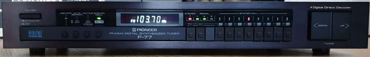
General information:
Good things:
Difficult, problematic items:
I meet till now 2 versions of this tuner: one with noise canceling filter-coil before the power transformer, which has a separate tuner PCB mounted on the mainboard, and the FM unbalanced connector is mounted separately on the rear cover and has no 300 ohm FM antenna input. The second one has no filter before the power transformer, all parts are mounted on the main board and the FM tuner is shielded, but has balanced and unbalanced FM input, and all of them with AM antennas are molded together and screwed to the chassis. I have the first version.
Deviation from the service manual: at audio output additionally has a 2.2uH coil in the signal path, followed by a 22pF capacitor to the ground on both channels. Unfortunately the service manual is incomplete, I did not found the whole specification of this tuner.
The tuner is very similar to the latest and famous F99X model, excepting the 2 IF amplifier stages, separate for Wide and Narrow IF circuits, for better selectivity.
The AM section uses a Sanyo LA1247, which has an improved subchannel signal/noise ratio as compared with the LA1245, and has an auto search stop signal.
Modifications:
Power supply: the power supply regulator originally was mounted on a heatsink, and generates enough heat to significantly raise the internal temperature of the tuner, which can degrade the tuner's alignment, especially of ceramic filters. For this reason, the regulator was mounted on the rear panel, electrically isolated (has the same potential, but to avoid any ground loop, I decided to isolate it), to dissipate the heat outside. The filter coil before the transformer was extended with 2+2 capacitors: 2x0.47uF/275Vac foil, and 2x2.2nF/2kV ceramic.
Changed values: C21 270uF/16V, C109 100uF/16V, C207 2200uF/25V Rubycon, C221 1000uF/25V Yageo, C319 100uF/16V, C322 47uF/16V, C415 received one more 2200uF/25V in parallel (location was already made on the PCB), C433 33uF/25V, R104 and R107 270ohms, R207 and R226 390k, 2.2uF mounted in parallel with R226, 10nF mounted in parallel with R103. Inductances inserted into power lines to decrease spurious interferences and noise between units: 100uH after C221, followed by a 270uF/16V, in the power line of TD6104 2.2uF, in the power line of uPD1163 2.2uH, and 10uH at the cathode of D425 and D416 for TC9147P (PLL + control).
Signal: for this, I considered the F99X schematic:
AM: C210 and C223 to 0.1uF foil Wima (improves the bass).
FM: R212 and R213 31.6k, R222 and R223 1.3k, R224 and R225 2.7k.
Other recommended changes: changing the ceramic IF filters (now have 2 same Murata with a blue body, red line mark on the top, and marking E10.7P) with low loss +-150kHz type (must be paired!).
Is a good tuner, recommended for improvements, and has a good, pleasant sound on FM and also on AM. Has a very musical sound!
Radiopribor n. S.P. Korolyov
Company was founded in USSR, Kiev (now is the capital of Ukraine) in 1953 for development and production of telecommunication measurement devices up to 40GHz as part of the Soviet Union's defense industry. In 1970 the factory became a leader in Soviet instrument engineering. It was named in honor of S.P. Korolyov for its contributions to the industry.In 1974 co pany had 149 different products, like ionization radiation register, phase sensitive voltmeters, counters, RF generators, frequency syntezators, non-linear distorsion meters, frequency standarts.
During the turbulent 1990s, the company preserved its technical potential, transitioning to new products and adopting international quality standards. Today, the entity operates as JSC Meridian n.a. S.P. Korolyov
Meridian RP-248

General information:
All electrolytics must be replaced promptly. C18 was reduced to 22uF/10V tantalum, whereas C45, C51, C56, and C64 were originally 30uF/6.3V and are now 47uF/50V according to the schematics. C49's 68nF was replaced with a 0.33uF foil capacitor, C57's 470uF was increased to 1000uF/10V, C39 is 4.7nF C0G ceramics, and C43 was reduced to 330pF. On the Russian tweaking page, it was recommended to reduce C39 to less than 150pF and completely remove the C43 - but the result was a constant oscillation of the amplifier section. The rest of the capacitor settings remain the same.
It produces a clearer sound on AM and FM than other pocket radios.
Realistic/Radio-Shack
Founded in 1921 in Boston by Theodore and Milton Deutschmann, RadioShack began as a mail-order retailer for radio enthusiasts before growing into an iconic American electronics chain. Acquired by Tandy Corporation in 1962, it expanded rapidly with its own-brand products (Realistic) and played a crucial role in the 1970s/80s personal computer revolution with the TRS-80. In the 1990s, it began to focus on wireless phones and de-emphasize the hobbyist market.
After multiple bankruptcies and ownership changes, including a pivot to crypto, the brand was acquired by Unicomer Group in 2023, which now operates it primarily as an e-commerce platform and dealer network.
RadioShack's legacy remains strong as the go-to spot for electronic parts for hobbyists during the 1970s-1990s.
Realistic/Radio-Shack Pro-29

General information:
ReVox
ReVox is a brand name, registered by Studer on 27 March 1951 for Swiss audio equipment for amateur recorders, while the professional machines retained the Studer name. The company moved to Löffingen, West Germany, in 1966, due to labor issues in Switzerland, but the building of a second factory was started in Regensdorf, Switzerland in 1967 - to open in 1968.
In 1967 the 36-series tape recorders ended with the G36, and were superseded by the transistorized A77 with a servo-controlled direct drive capstan. Over 80,000 36-series recorders had been manufactured. The A77, of which more than 460,000 were built, was complemented by an integrated amplifier (A78) and FM tuner (A76). The start of the 1980s saw the introduction of the "B7xx" series of high fidelity components, which was in turn replaced by the B2xx series in the mid 1980s. The B2xx series was versatile and feature-rich, all components containing microprocessors.
In 1990 Willi Studer sold the Studer Revox Group to Motor-Columbus AG, including all subsidiary companies. In 1991, Motor-Columbus split the Studer Revox Group into Studer (Pro), Revox (HiFi) and a Manufacturing-division. Motor-Columbus sold several subsidiaries and plants. The extensive reorganization culminated in the sale of the Studer Group to Harman International Inc., in March 1994. The Revox Group was excluded and sold to private investors. On 17 March 1994 Harman International Industries completed its acquisition and acquired from Motor-Columbus AG 100% of Studer Revox AG. Harman paid 100 Swiss Francs (approximately US $70.00) for all of the issued and outstanding stock in Studer Revox. Harman assumed post-acquisition indebtedness of Studer Revox of approximately 23 million Swiss Francs (approximately US $16 million).
ReVox A76
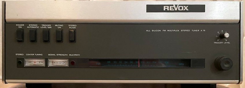
General information:
Because this radio's circuit is unconventional, below you can find a short description of circuit (translated from German from ReVox A76 in der Funkschau and shortened):
The input section features "dual gate" field effect transistors and quadruple variable capacitor tuning.
The FM demodulation is performed in a line demodulator. This consists of a driver stage with the differential amplifier (Q301 & Q303), two coaxial delay cables (with an electrical length of lambda/8 of the intermediate frequency) as load resistor, and a rectifier circuit (D301 & D302). In the arrangement, the frequency-dependent impedance of the line sections, one of which is short-circuited at the end (C308) and the other open, converts the FM into an AM. The line demodulator has the wide bandwidth of 5 MHz with good linearity. In combination with the wideband IF amplifier, a capture ratio of 1 dB is obtained, which gives excellent common mode selection. The operation of the line demodulator is completely uncritical, since RF balancing elements are missing. For AM suppression, only the limiting in the IF amplifier is decisive.
The subcarrier regeneration is characterized by an unusually high effort. The 38 kHz subcarrier is generated by a PLL circuit (phase locked loop). An oscillator with the differential amplifier Q405 and Q406 as active element generates a frequency of 76 kHz. After pulse shaping, this frequency is divided in an IC401 (MC790) integrated frequency divider with a divider ratio of 1:2:4. The resulting frequency of 38 kHz (subcarrier) controls the multiplex switching demodulator. The good symmetry of the switching frequency suppresses the SCA channel (background music, common in the USA) to a high degree even without a special 67 kHz cut filter. The 19kHz frequency passes from the frequency divider to a phase comparison stage (differential amplifier Q403 and Q404). In a broadband filter, the pilot frequency is filtered out of the multiplex signal and also fed to the phase comparison stage via the Q401 & Q402 differential amplifier. The bandpass filter has good phase stability and causes the pilot phase to rotate 90 degrees. Interference components of the pilot tone are kept away from the post-tuning circuit (capacitance diodes D402) of the 76 kHz oscillator by a 15Hz low-pass filter (R409, C408, R410). This arrangement acts as a narrowband pilot filter with a bandwidth of ±15 Hz. The bias voltage for the capacitance diodes is obtained at Z-diode D401. This type of subcarrier generation has the additional advantage that amplitude fluctuations of the pilot tone, caused by multipath interference, do not affect the stability of the subcarrier.
The multiplex decoder operates according to the splitting method. The multiplex signal is split for the main channel in the low-pass network (R508, C504, R509) and for the auxiliary channel in the 38 kHz bandpass (L501, C 501, R502). The auxiliary signal is amplified in stage Q501 and switch demodulated in Q503 and Q504. Switching demodulation was chosen because, in contrast to envelope demodulation, it transposes into the audible range only spurious frequencies that lie in the range of odd-numbered multiples of the auxiliary carrier. The first critical point is thus at 114kHz, which attenuates the deemphasis in the 38 kHz bandpass by 30 dB. Separate deemphasis for the main and auxiliary channels before multiplex demodulation has the advantage of strongly suppressing interference noise, such as whistling and chirping. The signal (L-R) or -(L-R) is generated on the resistors R518 & R519. The residues of the main signal reaching the switching demodulator, since they occur in phase at the working resistors, are eliminated by the common-mode suppression of the differential amplifier Q505 & Q506. This amplifier simultaneously operates as a matrix by forming the L and R signals, respectively, from the main signal amplified in transistor Q502 and the differential signal. Between the matrix output and impedance converters Q507 and Q508 are 15-kHz low-pass filters to suppress multiplex residual voltages. The level of the low impedance outputs is adjustable from 50 mV to 1V (75kHz swing).
The tuner I purchased had a few minor flaws: a missing metallic cover for the tuning knob, an obstructed signal level indicator instrument, one screw from the underside - all had been replaced or repaired. The signal level meter was fabricated using an analog instrument with the exception of the display component, which was retained in its original form. Additionally, the indicator was inclined at a 90-degree angle in order to be utilized in the horizontal position. While maintaining the same current and voltage (12V and 19mA, equivalent to one bulb of 24V/30mA utilized at 12V), the backlight was converted to four pleasant light LEDs.
By connecting the unbalanced input directly to the first stage of the tuner, after the 240 ohm impedance transformer, it is possible to enhance the signal while eliminating a 3 dB loss..
All electrolytics were altered: 50uF/25V was changed to 47uF/25V solide electrolytics for C114, C309 and C310 Oscon, and 47uF to 100uF/25V for C515 Elna SilmikII, C516 and C517, which convert 3.3uF/35V tantalum to 4.7uF/50V foil capacitors, C801 and C802 which apply 1000uF/63V elecrtolytic capacitors in parallel with 0.33uF/100V plastic capacitors.
At the power line input, I installed an EMI filter (Schurter 5500-1-55, comprised of two 560nF/275Vac components positioned before and after the line, as well as one 2.2nF/1kV ceramic component designed to filter a broader range of noise). In parallel with the contacts, two components of 2.2nF/3kV were added to the main power supply in order to eradicate the pop-up noise during switching On/off operation.
Despite this extremely unconventional circuitry, the sound is extremely delightful, warm, clear and detailed. The front plate is extremely conservative and uncomplicated; with the exception of the original set from Revox/Studer, the A78, it is difficult to locate a system that resembles it.
RFT
The origin of all companies that produced radios in Leipzig was founded in 1925 by the businessman Oswald Ritter and the technician Wilhelm Dietz. The company initially produced transformers, power amplifiers and dynamic loudspeakers under license from the American company Magnavox. From 1932 radio receivers were added to the product range and the company in Körting Radio, Dr. Dietz & Ritter GmbH changed. With the models Cyclo-Super and Hexodensuper, their first superheterodyne receivers, also called superheterodyne receivers, came onto the market. In the course of arming the Wehrmacht, D & R built radio technology for the Air Force under license from Telefunken and Lorenz on behalf of the Reich Aviation Ministry (RLM) from 1935. In 1938 Körting Radio was one of the leading manufacturers in the market. The Leipzig radio equipment manufacturing facility was affiliated to the Berlin Löwe Radio AG in April 1941 as Löwe Radio AG, Leipzig plant. From August 1, 1942, the Löwe branch in Melscher Strasse was called the Leipzig plant, analogous to the parent company Opta Radio AG. With the financial means from the outsourcing of his Wehrmacht production, Ritter continued the radio receiver production as the sole owner of the old factory at Eichstädtstraße 11 (today Untere Eichstädtstraße) under the name "Körting-Radio-Werke Oswald Ritter". The Opta operation in Melscher Strasse was named Opta-Radio AG, Stötteritz plant with the status of a SAG (Soviet state company) and in 1948 became VEB Stern-Radio Leipzig. In 1952, after an internal profile change, the name was changed to VEB Fernmeldewerk Leipzig, which was now mainly dedicated to the production of telecommunications systems, but also z. B. Manufactured microphones. The former Körting Radio Werke Oswald Ritter in Leipzig were initially incorporated into the RFT-Funkwerk Leipzig VEB and in 1964 the VEB Fernmeldewerk Leipzig. With the formation of the Kombinate, this company received the status of the parent company of the VEB RFT Kombinat Fernmeldewerk Leipzig in 1970.
RFT Capri 6401 Stereo
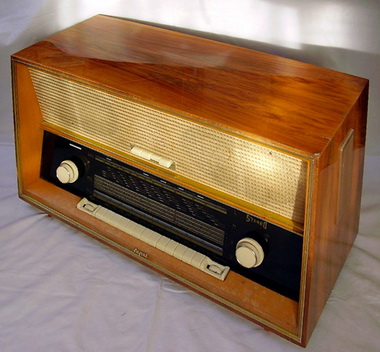
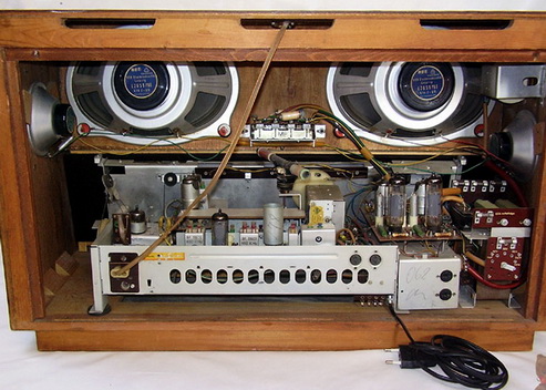
General information:
Modification: now has a power line socket with EMI filter + detachable power cable, and on DC filtering parts electrolytic capacitors were chanced with new ones.
Rotel
Rotel is a family-owned Japanese manufacturer of high-end audio and video equipment: home theater, amplifiers, compact disc players, etc. The company was established in 1961. In the early 1980s Rotel joined the B&W Group forming a strategic alliance with Bowers & Wilkins and later adding Classé Audio. The global affiliation between Rotel and the B&W Group dates back to the early 1980s with the establishment of exclusive distribution in North America and several European markets. Over the next 20 years, Rotel appointed virtually all Bowers & Wilkins distributors globally. In 2000 the B&W Group established Rotel Europe in the UK to consolidate all Rotel sales and support activities outside North America. The Classé brand was acquired by Sound United in 2018, breaking the link with B&W. Rotel maintains an exclusive network of specialist hi-fi dealers around the world.
ROTEL RX-850
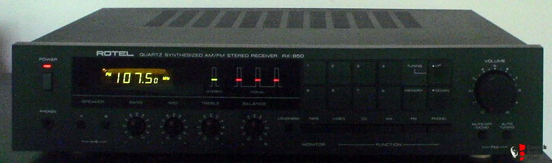
General information:
Good things:
Difficult, problematic items:
SABA
SABA (Schwarzwälder Apparate-Bau-Anstalt) began as a clock-maker in Triberg (Black Forest), founded in 1835 by Joseph Benedikt Schwer. In 1918 it moved to Villingen. Herman Schwer, the founder's grandson, started the manufacturing of headphones, radio parts, and a variety of products from radio components to receivers. It introduced for the first time on the market dynamic loudspeakers which soon became a bestseller. The company developed the first radio receiver with search and automatic fine tuning in all bandwidths. In 1968, SABA sold the majority of the company to GTE, an American telephone company. In 1980 the company was purchased by Thomson SA and integrated as a separate business unit. In 2010, Thomson finalized a restructuring leading to a better focus on its B2B activities and a change of its company name to Technicolor. The brand SABA remains in the ownership of Technicolor SA (ex-Thomson) which relies on several companies to manufacture and commercialize SABA products. Today, the products of the SABA brand are offered and sold in many European countries as well as in some other countries outside of the EU
Saba TS2030 RDS
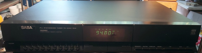
General information:
Good things:
Difficult, problematic items:
Sangean
Sangean Electronics, Inc. is a Taiwanese electronics company headquartered in Zhonghe District, New Taipei, Taiwan, with a factory located in Dongguan, China. Apart from products sold under its own brand names, which include Lextronix, Sangean also produces on behalf of other companies -> any of the shortwave radios marketed by Siemens, Panasonic, Braun, Grundig, C.Crane, and Roberts have been and are being developed and produced by Sangean. The organization is globally active with business units in Venlo, The Netherlands for Europe and Santa Fe Springs, California for the Americas. The business units are directly in contact with distributors in relevant areas. It is noted for its shortwave radio receivers and digital radio (HDR and DAB/+) receivers.
Sangean ATS-909
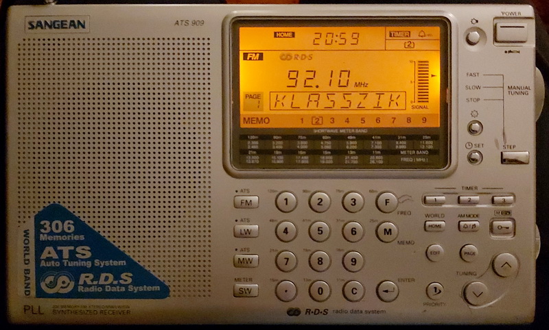
General information:
-
Shortwave bands (directly selectable):
Good things:
Difficult, problematic items:
I did not remove the alarm speaker, not made the anti-chuffing modification, I did not remove the detent in the tuning knob, not made finer tuning for SSB, 40Hz steps are enough for me.
In the case of FM, the frequency range can be increased or adjusted; see Erich Hoinicke's Modifications on Sangean ATS909 article (in German). Mr. Hoinicke mentioned that diodes put on the soldering side of the display panel can be used to adjust the receivable band of OIRT (64.0...74.0MHz) or BOS (76.0...87.5MHz). Please refer to his article for further information.
Modifications:
Improving AGC: C57 changed from 22uF to 10uF, C11 changed from 10uF to 4.7uF (as in the service manual), and R181 changed from 100k to 470kohm.
Modification for better audio: the speaker was changed with a speaker of ATS9009X. C80, C93, C94, C106, C107, C132, and C133 changed to 10uF, C110 and C111 to 330uF, C116 and C117 to 1000uF, C130 and C131 to 4.7uF.
Modification in power line: C76 changed to 100uF/16V, C99, C100 and C193 to 470uF/10V, C192 270uF/16V, all dry electrolytes. C95, C184, C189 to 4.7uF/35V X7R SMD MLCC,
All electrolytes in my set were Su'scon SL 85-degree type (the same capacitors are used by Denon in their devices, CD/DVD players, and tuners from the same period). Half of them were still good, others with higher leakage and increased ESR. All were changed with Yageo (in signal path) or solid/dry electrolytic capacitors (in power line). LED backlight was changed with orange LEDs.
Is a good set for modification. Now the sound is much better, but not as of ATS-909X model. Is one of the best portable on LW, MW, and FM, but on SW cannot beet the SONY ICF-SW7600GR or the Panasonic RF45B.
Sangean PR-D1
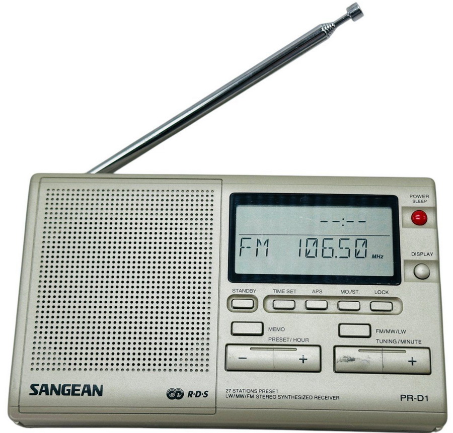
General information:
Good things:
Problematic items:
When comparing the radio's parts to the schematics, it can be seen that the C16 and C55 installed on pin 6 of the AN7117 amplifiers circuits instead of 100uF/10V are 220uF/10V (while the datasheet suggests 330uF/10V).
Modifications: ceramic filter changed from L10.7S with a Murata 10.7MJ type, and all electrolytic capacitors.
Sangean DT-220
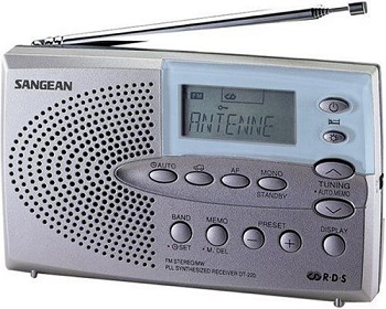
General information:
Problems:
At its time was one of the smallest receiver with RDS capability, used for RDS reception checking and signal transmission accuracy/level by Hungarian Radio authorities in 2000-2006.
One weakness is the volume potentiometer: rapidly became unusable giving scratch noise in the speaker. Temporary can be "refurbished" with contact spray, but is better if you change it asap (R-VR 20kA, part number: 1312014).
Some parts are also different from schematic: C44 instead of 220uF/6.3V is 470uF/6.3V, CF2 instead of Murata 10.7MS3 is L10.7S Chinese type.
Modifications: ceramic filter changed from L10.7S with a Murata 10.7MJ type, and all electrolytic capacitors, excepting the 2 audio output ones, were changed because of their high loss (>2%) and high ESR (>2 ohms) (after 9 years usage), with same capacitors value TA type (4,7uF/16V; 10uF/16V and 47uF/6.3V).
Sangean DPR-69+
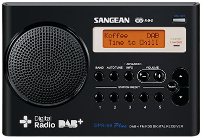
General information:
Good things:
Difficult, problematic items:
Inside the capacitors were manufactured by GD (China), SH7 type, 105C degree. All are in good condition (my set was made at end of 2016).
Not so many articles or reviews can be found about this radio, neither service manual. Look similar to Sangean DPR-67. As a guideline, I used the service manual of Sangean DPR-99 (construction, units are the same, but use different integrated circuits).
Is overpriced, in 2021 the unit is sold for 79-110 Euro, on the used market costs 20-40 Euro.
Sangean ATS-909X
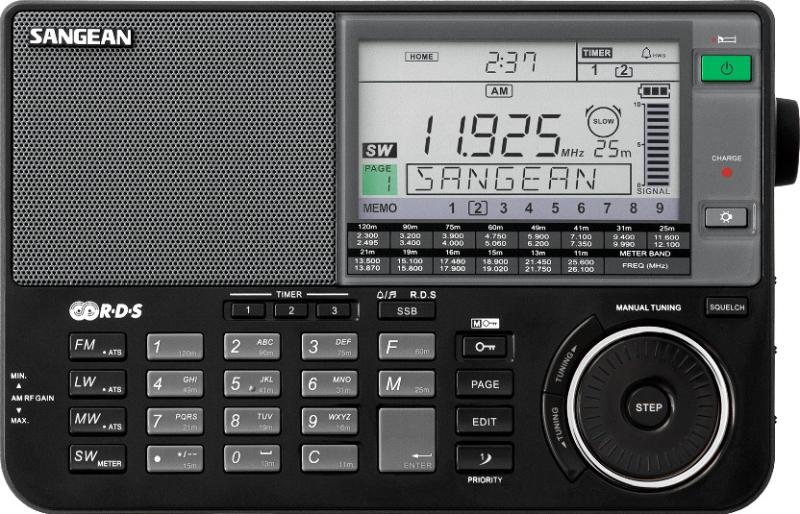
General information:
-
Shortwave bands (directly selectable):
Good things:
Difficult, problematic items:
Sansui
Sansui Electric Co., (Sansui Denki Kabushiki-gaisha) was a Japanese manufacturer of audio and video equipment. The company was founded in Tokyo in 1947 by Kosaku Kikuchi, who had worked for a radio parts distributor in Tokyo before and during World War II. Due to the poor quality of radio parts Kikuchi had to deal with, he decided to start his private radio part manufacturer facility in December 1944 in Yoyogi, Tokyo. He picked transformers as his initial product line. Kikuchi's thought was "Even with higher prices, let's make the higher quality of products." In 1954 manufacturing Pre-Amp, Main-Amp kits, as well as finished amplifiers which used tubes, was started; in 1958 Sansui introduced the first stereo tube Pre- and Main amplifiers. By the 1960s Sansui had developed a reputation for making serious audio components. They were sold in foreign markets through that and the next decade. As the mid-1980s arrived, sales were lost to competitors (Sony, Pioneer, Matsushita's Technics). Sansui began to lose visibility in the United States around 1988 and then focused on manufacturing high-end components in Japan. The company began to manufacture high-end television sets and other video equipment but ceased exportation. Sansui ended its Japanese production of high-end amplifiers sometime between 2002 and 2005 and went out of business in 2014. In Japan, consumer product maker Doshisha has the right to manufacture and sell under the Sansui brand. Outside of Japan, the brand belongs to Nimble Holdings of Hong Kong.
Sansui T-500L
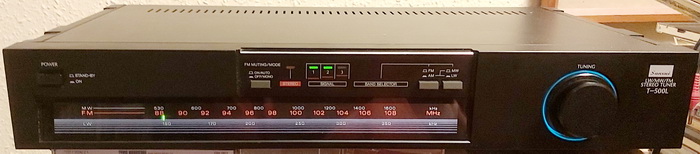
Is a nice tuner from the lowest family of System IS, part of IS-500. Its specification (excepting the quieting sensitivity at 50dB, which is 17.0dBf, compared to 16.5dBf) all specifications are the same with the higher family tuners, the T-700 and T-900. The pointer light's color is the tunning indicator: during searching is red, but if the tuner is rightly on the station, became green. The tunning knobs' blue backlight is phenomenal.
General information:
To be considered: no fuses are mounted inside of the tuner (they are shorted with wire). The transformer is continuously connected to the power supply, and the power switch connects only one secondary coil's voltage to the tuner circuit. The mQ1 regulator transistor stabilizes the input DC voltage from 18.5V to 13.5V - and the heatsink remains almost cool after several hours of operation.
Modifications:
Power circuit: mC3 from 470uF/25V to 2200uF/25V, mC4 from 330uF/16V to 470uF/35V, mC5 from 10uF/16V to 390uF/35V, dC36 from 220uF/16V to 470uF/35V, eC24 from 100uF/16V to 330uF/16V.
All electrolytes from the signal line were changed to polypropylene. The audio output capacitors (mC48L and mC48R) value was changed from 0.15uF/100V to 0.47uF/63V. Other below 10uF were changed to solid electrolytes or tantal capacitors.
The tuner is built from modules, like AM IF module, FM IF module, MPX module, signal level meter module, etc, and all are soldered to baseplate - not via sockets! This is a cheap solution but is a nightmare if you would like to repair any of them or to change all electrolytic capacitors. On the base plate are no components, just soldered modules. The straps which connect them are printed on the soldering side, on the top side can be seen a drawing of patterns from the bottom side, making it easy to recognize the trace. Also, the tuner has an electrolytic, which can be changed without desoldering the whole unit from the baseplate, because below the tuner module the baseplate has a cropped part, which easily can be permanently removed. The removed area has no trace or coverage with cupper - but by removing it you can change only one 10uF/50V capacitor from the tuner module.
Sanyo
Sanyo was founded when Toshio Iue the brother-in-law of Konosuke Matsushita and also a former Matsushita employee, was lent an unused Matsushita plant in 1947 and used it to make bicycle generator lamps. Sanyo was incorporated in 1949; in 1952 it made Japan's first plastic radio and in 1954 Japan's first pulsator-type washing machine. The company's name means three oceans in Japanese, referring to the founder's ambition to sell their products worldwide, across the Atlantic, Pacific, and Indian oceans.
Sanyo FMT-30L
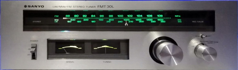
General information:
Good things:
Problematic things:
The schematic is similar to the FMT 301 model: the tuner, the FM IF the MPX demodulation, and the power part are the same. Differences can be found in: the IF buffer stage between 10.7MHz ceramic filters, air check signal generator, and the whole AM circuit, including the LW, which cannot be found in the FMT 301 model.
The power is separated: 10.2Vac for bulbs (3 pcs of 12V/60mA: 2 for the scale and one for instruments), and 19Vac for the whole radio circuit. I purchase it with both scale bulbs burned. Both were replaced with 6-6 warm LEDs, each formed by 3 groups of 2-2 LEDs reversed in parallel connection including 22uF MLCC, and finally in series with one 33 ohm resistor (0.5W). The result: no vibration can be seen, is completely like a bulb's backlight.
The FMT30L has 3 gangs on the FM part with a FET front stage, and 2 gangs for AM, 1+2 (in total 3) 10.7MHz ceramic filters with one IF amplifier between them. The MPX decoder is made with the famous LA3350 with 1-1 buffer formed with one PNP transistor stage at outputs and is DC coupled with the output of MPX demodulator IC.
All electrolytic were capacitors replaced. Changed values: C26 , C61 and C63 470uF/35V Nichicon, C60 1500uF/25V Kemet ESW, C46 270uF/16V Oscon, C69 to 100uF/16V Oscon. C27, C41, and C42 now are 1uF/53V ERO foil capacitors.
The sound is full of bass - I think excessively, but is very pleasant, similar to Marantz 2100.
Sanyo FMT-611LU (Expert 1640)
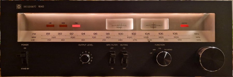
The Sanyo FMT-611 and Expert 1640 aren't different models; they are the same tuner, often sold under both names, with "Expert 1640" being a regional or rebranded version, especially in markets like Germany, known for strong stereo reception and features like MW/LW bands.
A sizable slanted scale, a wave/function selection, a muting and MXP filter switch, an output level control knob, and a power button are all located on the front. The main voltage selector (110/220Vac), RCA connections for the audio signal output, an AM ferrite rod antenna, power cord, and external antenna connectors (for AM and FM), are located on the rear side.
General information:
Good things:
Problematic things:
The scale is luminated by reflected light, and the meters are lit from the center. The stereo mode and the received wave also provides a bright feedback. Like all sets from this era, the set has a lot of space inside, and it also features a very well-designed traditional front.
Modifications:
1. Installed the powert switch befor the transformer, followed by an EMI filter between them, installed under main transformer. (2.2nF/2kV+10nF/1kV+0.68uF/630V+2x16.8mH+10nF/2kV+10nF/1kV+0.68uF/630V). The main switch is a 250V/2A type with 2 circuits - suitable for this.
2. Four more screws were added to the bottom plate, which already had holes in it. There isn't any noise coming from the transformer.
3. I thought the voltage regulator's design was really bad, so I altered it. After rectification, the primary transformer delivers 38Vdc. The voltage, which is 32Vdc after the regulator and capacitor multiplier, is utilized for LW-MW band selection relays and to power the output audio buffer following the MXP circuit. The tuner circuit use 13Vdc and 10.5V/30mA for stereo lamp - both voltages are made from the 32Vdc via resistors dissipating the excess energy, heating the tuner circuits from inside. Because of this, R05 were changet to 100 ohm/2W, a real one-transistor voltage regulator was obtained after the capacitor multiplier (reusing the D05, adding a 2SD325 npn transistor, one 3k resistor and 100uF/25V in parellel with the Zener diode); the power PCB includes vacant patterns for this, including two series-connected 1N4001 diodes and one 47 ohm resistor for the stereo lamp. Power-dissipating resistors have been eliminated.
4.Every bulb was connected in parallel to a separate transformer coil. I installed one NTC 2.5 ohm on seriaes with all bulbs to protect them because the power line voltage in the now EU is 230Vac+-5%, which is more than the nominal voltage that the radio recommends. 5. Each rectifier diode received a 0.022uF ceramic capacitor to reduce noise, and each of the primary power filtering capacitors (C01, C02, C03, C04, and C16) was given a 0.1uF ceramic in parallel.
6. Variations in capacitor values: C01 1000uF/63V, C02 220uF/50V, C03 and C04 470uF/35V. C17 390uF/35V, C16 1000uF/35V. C18 was modified to 0.33uF/100V in accordance with the LA3350 datasheet.
The sound is warm, detailed, clear. I think is a very underestimated tuner.
Sharp
/ Optonica
Sharp Corporation was founded in 1912 in Tokyo by Tokuji Hayakawa as a metal workshop. In 1923 the company was relocated to Osaka and began designing the first generation of Japanese radio sets. The company was established as "Hayakawa Metal Works" in 1924, in Tanabe-cho, Osaka. In 1942, the name was changed to "Hayakawa Electric Industry Company". The Optonica brand was created and first launched by Sharp in 1976 to compete in the high-end audio market along with established brands such as Sansui Electric, Sony, Panasonic, Sanyo, Yamaha, Nakamichi, Onkyo, Fisher Electronics, Technics (brand), Pioneer Corporation, Kenwood Corporation, JVC, Harman Kardon, and Marantz. The brand was designed and built by Sharp, not contracted out to another supplier, and all of the items offered were of high quality standards and built in Japan. Sharp Corporation was responsible for marketing the products. Marketed for a few years, the line and brand were discontinued in 1991.
Sharp Optonica ST-1122H
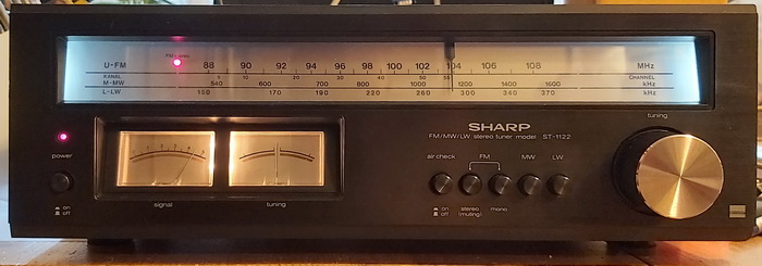
General information:
Good things:
Problematic things:
Sharp Optonica ST-1616H
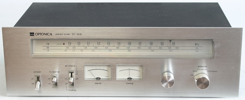
General information:
Good things:
Problematic things:
Modifications:
All electrolytic capacitors changed, in audio with pp, in power line below 100uF with solid electrolyte type.
R117 received in series one 10uH coil, R304 one 100uH coil, and the ZD401 is connected to the base of Q401 also via 10uH coil. R405 was removed.
Some capacitors value was changed: C212 to 470uF/35V, C314 100uF/25V solid electrolyte, C404 to 2200uF/25V, C405 to 470uF/35V, C406 to 390uF/35V, C419 to 470uF/35V.
Siemens
Siemens & Halske was founded by Werner von Siemens and Johann Georg Halske on 1 October 1847. In 1848, the company built the first long-distance telegraph line in Europe; 500 km from Berlin to Frankfurt am Main. In 1867, Werner von Siemens described a dynamo without permanent magnets. A similar system was also independently invented by Ányos Jedlik and Charles Wheatstone, but Siemens became the first company to build such devices. In 1881 the company continued to grow and diversified into electric trains and light bulbs. Siemens & Halske (S & H) was incorporated in 1897, and then merged parts of its activities with Schuckert & Co., Nuremberg in 1903 to become Siemens-Schuckert. In 1919, S & H and two other companies jointly formed the Osram lightbulb company. During the 1920s and 1930s, S & H started to manufacture radios, television sets, and electron microscopes. In the 1950s, and from their new base in Bavaria, S&H started to manufacture computers, semiconductor devices, washing machines, and pacemakers.
Siemens AG today is a German multinational conglomerate and a focused technology corporation headquartered in Munich and the largest industrial manufacturing company in Europe with branch offices abroad. The principal divisions of the corporation are Industry, Energy, Healthcare (Siemens Healthlineers), and Infrastructure & Cities, which represent the main activities of the corporation.
Siemens RH-300
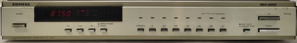
General information:
Good things:
Problems:
The accessible service manual (Indent-Nr. 535037) does not cover the entire tuner circuit; several component values and the PCB are slightly different. Examples include C51 values of 22uF instead of 10uF, R28 and its region on the PCB being different, and errors such as TD6104 being designated as TC6104, among others.
Capacitors are in medium condition, having been in use for more than 40 years.
Has two voltage regulators: the first supplies the radio circuit (AM and FM), which includes the audio signal component. The second regulator powers the entire digital, display, and control components. To improve power line noise cancellation, I added inductors to the power lines of each integrated circuit and the FM tuner (FM part 3.3uH, AM-audio-digital-display part 100uH).
Capacitors changed: C115 1000uF/25V, C205 2200uF/25V, C206 390uF/35V, C208 270uF/16V, C132 270uF/16V. All electrolytic capacitors between 0.1 and 4.7uF were converted to foil capacitors. Conclusion: is an average tuner with low signal-noise levels (the audio signal passes through three LC circuits!). For me, there is a lack of bass (which can probably be accounted for by raising the capacitors values in the signal route), but the clarity of the sound is satisfactory.
Siemens RH777
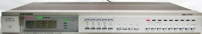
General information:
Good things:
Problems:
Differences from the service manual: all three main PCBs (control with power supply, subboard, and tuner board) appear to be in the design phase, with several options, unmounted but numbered pieces that are not included in the schematics. They may be from Japanese or other countries' models, which have unique requirements. Only one more component was discovered, with no position number: a 0.1uF tantalum capacitor between pin 3 of IC5 (TA7324) and ground.
Modifications: instead of C86 and C87 (both 4.7uF in series), I placed a 2.4uF pp capacitor, and instead of C88 and C89 (both 1uF in series), I mounted a 0.49uF pp capacitor. In some locations along the power line, I increased or maintained their values, but I installed solid electrolyte capacitors.
I installed pp capacitors in the audio signal path, and their values were increased from 2.2uF to 4.7uF right at the output.
Siemens RK 621
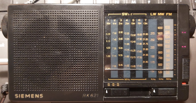
General information:
-
Shortwave bands:
Good things:
Problems:
After changing the high capacitance electrolytics to solid electrolytic capacitors, the sensibility increased significantly. Those were dried: ESR between 0.5-5 ohms, and loss higher than 3%. Surprisingly, have no contact problems on band selectors.
Compared with Sangean SG-789, the Siemens RK-621 selectivity, sensitivity, sound is better.
Siemens RK 747
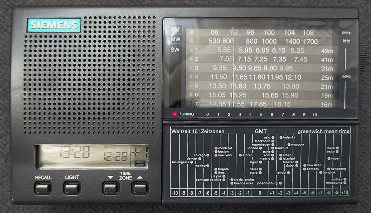
General information:
-
Shortwave bands:
Good things:
Problems:
Sony
In 1946, Masaru Ibuka started an electronics shop in Shirokiya, a department store building in the Nihonbashi area of Tokyo. On 7 May 1946, Ibuka was joined by Akio Morita to establish a company called Tokyo Tsushin Kogyo (Tokyo Telecommunications Engineering Corporation). The company built Japan's first tape recorder, called the Type-G. In 1958, the company changed its name to "Sony". The name "Sony" was chosen for the brand as a mix of two words: one was the Latin word "sonus", which is the root of sonic and sound, and the other was "sonny", a common slang term used in the 1950s America to call a young boy. In 1950s Japan, "sonny boys" was a loan word in Japanese, which connoted smart and presentable young men, which Sony founders Akio Morita and Masaru Ibuka considered themselves to be. At the time of the change, it was extremely unusual for a Japanese company to use Roman letters to spell its name instead of writing it in kanji.
Sony played a major role in the development of Japan as a powerful exporter during the 1960s, till today. It also helped to significantly improve American perceptions of "made in Japan" products. Known for its production quality, Sony was able to charge above-market prices for its consumer electronics and resisted lowering prices.
Sony's TR-63 radio "cracked open the U.S. market and launched the new industry of consumer microelectronics. By the end of 1968 Sony, in one year, sold more than 5 million units of portable transistor radios in the USA.
As a major technology company, it operates as one of the world's largest manufacturers of consumer and professional electronic products
Sony STR-7055A
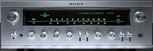
General information:
Good things:
Difficult, problematic items:
The radio on AM are with 2 gangs, on FM are with a 4-gangs variable capacitors, two IF amp stages, 2 pcs of 10.7MHz ceramic filters, and a Sony-made low-pass filter at radio output. At that time the new unit price was 1198 DM.
Sony STR-4800
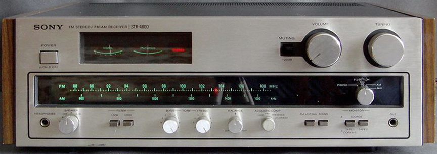
General information:
Good things:
Difficult, problematic items:
The ceramic filters are Murata type, SFJ10.7MA with 4 terminals and blue dot (10.67MHz). The transformer is well shielded, without noise. The volume potentiometer was necessary to be replaced, sometime gives scratchy noise. The scale pointer was made with LED, which is a miracle at that time!
The capacitors were mostly Sam Wha type, and just a few of them were Korean Chemical Com. I bought it with one amplifier channel dead. Root cause: one capacitor from the amplifier feedback network was dead (instead of 100uF I measured 2nF, completely dried). For that and regarding past 45 years, all electrolytes were changed. The first time I used dry electrolyte capacitors in the audio stage (470uF/6.3V, Oscon), and they do not influence the overall sound impression.
At that time the new unit price was 1120 DM.
Sony ST-J60
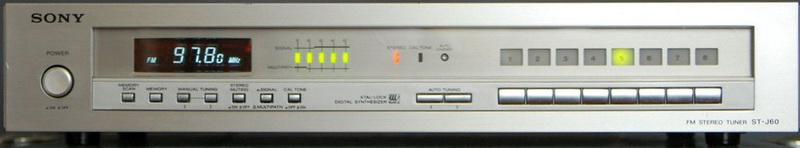
General information:
Good things:
Difficult, problematic items:
The tantalum capacitors from the audio signal path were changed to foil capacitors (4uF, respectively 10uF type, all Remix type from the end of '60s). In tuner and digital part capacitors with 16V nominal voltage now are dry electrolyte type, in the rest of power line Yageo, CapXon, and Rubycon elecrolytics.
The metalized-paper capacitors from the main switch were necessary to change it immediately: were cracked, dried, and their capacitance instead of 22nF was a few hundred pF (between 100-310pF) -> changed to 10nF/1kV ceramic type. After the power switch received an EMI filter (.68uF+2x7mH+.68uF+2.2nF).
The best thing about this tuner is its clean, retro-futuristic styling, fine ergonomics, and the fact that this long-lost, once-high end design can be picked up for pennies now.
Now the sound is equilibrated in the whole spectrum. I recommend it as an FM tuner in your high-end, because can beet the Sony's with big front, and almost any modern tuners from today.
Sony STR-232L
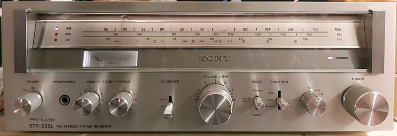
General information:
Good things:
Difficult, problematic items:
The construction of the receiver is very stable and excepting some stiffening plates, which cover some parts of the PCB on the soldering side, you have easy access to all components.
The ceramic filter is TAIYO type, CF-107-D with 3 dots on the top's left side: red, silver and orange. Contain 2 group of double (in total 4) ceramic filters, and has 4 pins, 2-2 on both ends.
The transformer is impregnated in a plastic house, without noise - not shielded.
All capacitors were Elna type. Is interesting, the pop-up circuit without relay, just with a delay signal to the audio power ICs.
The used radio circuits, the CX168 and CX178, are soo old, cannot be found any datasheet about them on the net - just some block diagram in the service manual.
Is a nice, small unit, with relatively low output power, which sounds much more better than any current mini Chinese amplifier. Should be used with speakers which have higher impedance then 8 ohm!
Sony ST-JX3L
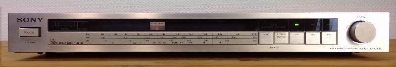
General information:
Sony ICF-7600AW
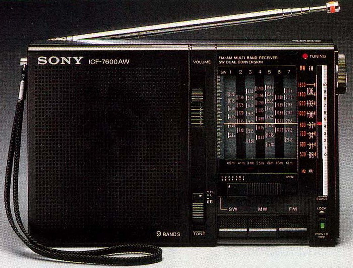
General information:
Good things:
Problems:
My set was made in Japan, inside of set and also on the package box has the same serial number (125792), but the FM coverage is 76-108MHz. That means should be a Japanese version, an ICF-7600A model instead of ICF-7600AW (probably the previous owner changed the hod). This makes a bit difficult to set the radio to a certain frequency because the scale is marked from 88 to 108MHz, and I use the range of scale from 96 to 108 MHz for the rage 88-108 MHz. The selectivity is very good, and cannot be heard any adjacent channel.
Sony ICF-7600D

Sony introduced the ICF-7600DS/ICF-2003 in 1987, an upgrade of this model, in a new anthracite/dark grey chassis, aubergine-colored AM/FM function and band buttons, and the EXECUTE button, as well as the correction of the majority of design flaw in the previous model.
The telescopic antenna may be swiveled onto the top of the unit, and a jack socket allows for the installation of an external antenna (excluding the German model). Just above it is a little attenuation switch. The ICF-7600DS lacks an RF gain control, which might result in overload when used with long-wire or broadband amplifying active antennas.
It is powered by six UM-3 batteries, two of which are used for memory and clock tasks, and lasts a long time. The remaining four batteries for radio operation last around 12 hours. To save batteries, utilize the included mains adaptor AC-240. The Sony 7600D's reception ability was exceptional for a compact receiver when it was first released (in 80's), and it remains an above-average portable radio today. Suboptimal sensitivity is less obvious in Europe, which has a higher density of high power transmitters and field strengths than Africa or the Pacific area. The built-in IF filter can effectively distinguish transmitters in 5 kHz channel spacing, particularly when fine tuning is employed when the set is tuned 1 - 2 kHz low or high. It was replaced by the ICF-SW7600 model.
General information:
Good things:
Problems:
Raw receiving performance is fairly close to that of the ICF-SW7600 on shortwave. SSB is even more difficult to operate than on the SW7600. FM has strong sensitivity but weak selectivity.
Changes stated by Sony supplement: "The circuit has been changed to reduce the drift of the 2nd local oscillator, and the location of some parts on the printed circuit board has been changed." Positions are identified based on the their position on the original schematic/supplement:
Typical defects: high battery drain - change transistor Q32 (2SB1013).
Modifications:
Poor auditory response: the original has overly muffled sound on both tone positions (News and Music) - and this is a design issue. The audio band is determined via a sophisticated feedback RC network, which is controlled by the Tone switch. Checking, it turns out that the audio band was fairly limited, particularly in the 400-2kHz region also for FM. Changes: C31, C33, C89, and C93 2.2uF/10V TA, C91 3.3nF, C97 0.1uF/63V pp, C98 470uF/10V, C99 470uF/10V, C100 47uF/16V, C101 68uF/16V, C102 12nF pp, C103 1.5nF pp, C104 15nF pp.
Other changes: 4.7uF/35V MLCC in paralell with D30, L22 and L23 can be replaced with one small EMI filter (2x10mH/1A), C158, C214 330uF/6V TA.
Coverage: There are two solder jumpers between D205 and D206. If the one from D206 is removed, we will have expanded SW, which means coverage up to 30MHz. If the jumper from D205 is removed, we can achieve full FM coverage, which ranges from 76MHz to 108MHz.
FM filter modification: Use low loss 180kHz (SFE10.7MS3) or 150kHz (SFE10.7MJ) filters. After a filter mod, the IFT T3 should be adjusted to provide the best sensitivity and lowest distortion. Frontend alignment may also be worth considering (T1 and CT1 for first tracking, L20 and CT2 for second tracking); improving it solely for 87.5 to 108 MHz will undoubtedly result in improved tracking and thus sensitivity in the FM broadcast spectrum. The discrete ratio detector should also be aligned to match the filters in order to get the highest sensitivity and lowest distortion with IF T4 and T5.
Dual gate second mixer: 7600D/2002 was found to suffer from oscillator pulling on strong SSB stations. Can be solved replacing the 2nd mixer JFET by a dual-gate FET with the input signal and LO signal being fed to one gate each. Not exactly a beginner's mod.
In general, all electrolytes should be replaced.
For this radio description, adjustments and modification (excepting audio parts) I used Stephan Grossklass's website.
Sony ICF-2001D
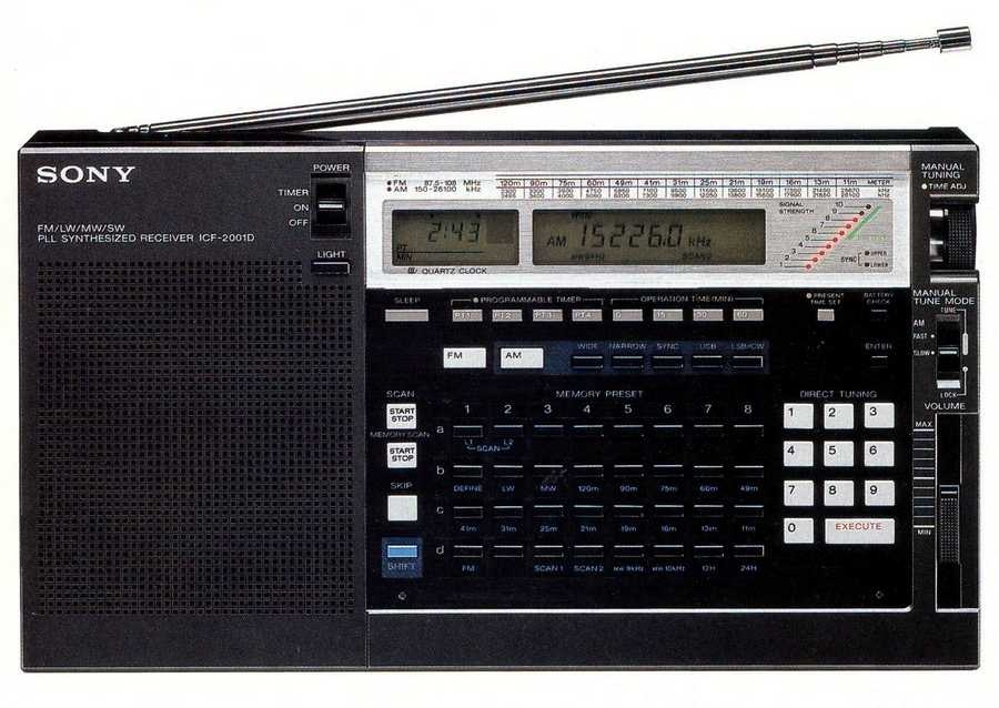
The ICF2001D has wide coverage. It can be operated continuously between 150 kHz, right up to 29,999 kHz, that includes long wave, medium wave, and shortwave. Exists some version with extended FM - from 76 to 108MHz, or air band coverage from 116 to 136MHz. If you press and hold a key marked SHIFT, the blue colored functions become active, and for the most part it means you can get the set to jump immediately to the bottom of the longwave, medium wave, the 120, 90, 75, 60, 49, 41, 31, 25, the 22, 19, 16, 13, 11 meter shortwave bands, plus the FM and airband (if you have that version). Built-in 24 or 12 hour clock, and the versatile timer (0, 15, 30, 60 minutes). SSB operation (LSB or USB), synchronous detector, RF gain control, etc.
General information:
Good things:
Problems:
Display viewing angles are best when looked at from the bottom. The display backlight is microprocessor controlled and automatically delays its timeout if any of the (electronic) controls are used while it's on. The lighting itself with a single green LED on the right-hand side has a very low light intensity. The smoothly turning tuning knob with an optical encoder (at least it feels like one and is not jumpy) is nice to operate. Carrying the set is a little awkward. My set came without the shoulder strap but I wouldn't consider that to be terribly useful either. A handle would have been useful.
The ICF-2001D was succeeded in by the ICF-7600D, and in 1986 by the slightly improved ICF-7600DS.
I have the (modified?) German version of this set, means the frequency coverage is 150 - 29999 kHz; 87.5 - 108 MHz, no Air Band; SSB reception and external antenna connector and the frequency band really shows 150-29999 kHz. The original German version's AM coverage should be 150 - 26100 kHz. The versions can be identified by the missing AIR BAND button and by the frequency band information above the clock display.
Important:
I got the set with an external switching power supply. As a result, when using this power supply, the MW sensibility was very low, but I could not hear any stations on the LW, and I could only receive 2-3 stations on the entire SW band. When I changed the set to a standard wall plug with transformer and unregulated filtering, but improved with extra filtering capacitors (instead of 1000uF/16V I installed 1800uF/16V+3300uF/16V+0.1uF/50V MLCC) and an EMI filter (2x6.6mH), the entire set came alive. Another interesting point: when repairing or refurbishing radios, I use a Fluke 187 digital multimeter. Now listening to one station on MW 756kHz, I heard a whistling sound of 1-2kHz above the signal. This sound went away after I switched off the multimeter. Conclusion: never use a switching power supply for AM reception or a digital multimeter during radio-tests. :-)
The ICF-2001D was and remained one of the most successful and best performing portable shortwave receivers.
Sony ICF-7601L
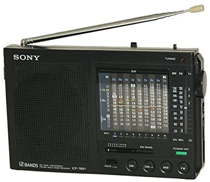
General information:
Good things:
Problems:
Sony ICF-SW7600
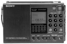
As the successor to the ICF-7600DS, Sony introduced the ICF-SW7600 at the end of 1989, a new representative of the receiver group, with the number combination 7600 in the type designation, which did not reduce the confusion surrounding the device versions. The telescopic aerial is pivot-mounted on the top of the device, and for the first time the receiver was equipped with a flap at the rear, with which it could be brought into an inclined position for operation. The left half of the front panel is taken up by the loudspeaker grille, on the right is the frequency display and the slide switch, next to it the number buttons for memory recall or direct frequency input and the AM / FM / EXECUTE buttons. The frequency is displayed with an accuracy of 5 kHz, and the corresponding meter band is also displayed for frequencies within the limits of a shortwave broadcast band. A small red LED next to the display serves as a field strength indicator and lights up when the signal is strong. The device is switched on by pressing the ON button; in the LOCK position, the slide switch is locked to prevent accidental switching on in luggage.
General information:
Good things:
Problems:
Defects:
How I recognized which capacitors must be changed?
What kind of capacitors I used?
Tantalum has its own advantage: because mostly are used for filtering (power supply or bypass), are better than electrolytics in this position.
Difficulties, what I meet:
Sony ICF-SW30(L)
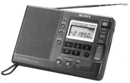
General information:
Good things:
Problems:
Regarding small size, I recommend to change the normal electrolyte capacitors with solid electrolytic capacitors.
Sony ICF-SW7600G
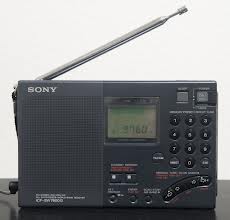
General information:
Good things:
Problems:
In this radio I corrected/modified just 4 things:

Modification: the unconnected pin of S4-1 with a wire are connected to out of C449, shortening it in Music mode, the signal goes just through C450 - coupling the amplifier via 1uF instead of previous equivalent 66nF.
With this easy modification and with changed output capacitors the sound became more pleasant. Can be heard the difference when you select on the Tone switch the News or Music on FM, and sounds like the old predecessor, the SW7600.
Sony ST-SE500
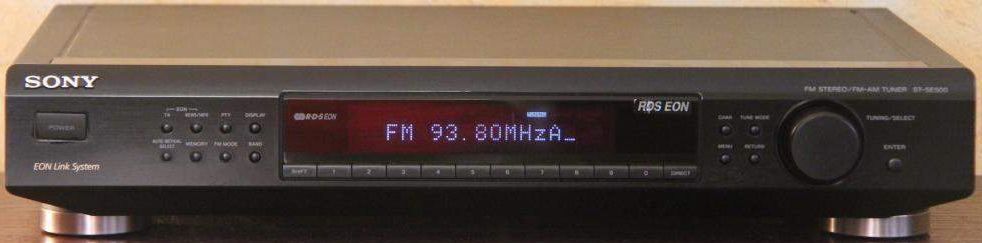
General information:
Good things:
Problems:
The tuner section is pretty straightforward: on FM, there has 3 gangs, followed by 2 ceramic IF filters (both Murata 10.7S with a red dot on the top-left side), and on AM, there are 2 gangs.
Changes: I installed an EMI filter (0.47uF+2x12.4mH+1.5uF) between the power switch and the transformer because it is a must for modern tuners. The switching power source of my laptop or an LED bulb no longer interferes with MW reception. In the RF PCB tuner supply supply circuit 220uF -> 270uF/16V, ICs supply (LC72130 and LA1851) 47uF -> 100uF/16V. From the main board changed capacitors: C205 100uF/16V, C319 470uF/35V, C809 270uF/16V, C905 330uF/50V, C909 390uF/35V. The power line of IC201 (FM IF) and IC802 (RDS) received 1-1 coil of 2.2uH for noise suppression.
Is a decent general-purpose tuner with the potential for RDS/EON RT, but nothing special. Compared to the features and electronics of other models, I believe was a little overrated.
Sony ICF-SW11
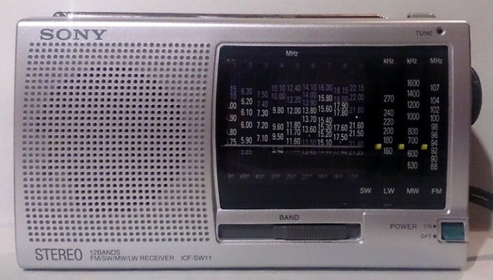
General information:
Good things:
Problems:
Modifications:
First time I used solid capacitors on power audio output (generally are designed for power line filtering), and the result is good: C61 100uF/6.3V and C66 470uF/6.3V both replaced with 470uF/6.3V OSCON. In this radio C60 470uF/6.3V was replaced with 470uF/6.3V OSCON, and the C52 100uF/6.3V filtering capacitor of RF IC1 was also replaced with 270uF/16V OSCON. All the rest of the electrolytics were replaced with the same value TA types. The ripple rejection capacitor C45 instead of 10uF/16V was replaced with 22uF/25V TA (in Philips AE3405 are used 47uF). R16 instead of 15k mentioned in service manual, have 150kohms value, and between pin 25 and 28 of CXA1238 (IC1) was inserted a 220kohms resistor - improving the AGC and the muting (like in Panasonic RF-B11). The used FM IF ceramic filter (230kHz type) was replaced with Murata 150kHz low loss type (SFE10.7JA Murata). The R29 10 ohms resistor was changed to 39uH/2.5ohms coil in power line of IC1.
With above mentioned modifications, via headphone, you will get a small monster, detailed audio band on FM with reach bass and smooth trebles.
If you need a stereo indicator, easily can be made: connect one resistor of 2.2kohms to pin 4 of CXA1238, and on other end connect the cathode of a red LED, and the anode to the power supply (B+ 3V).
Sony ICF-SW7600GR
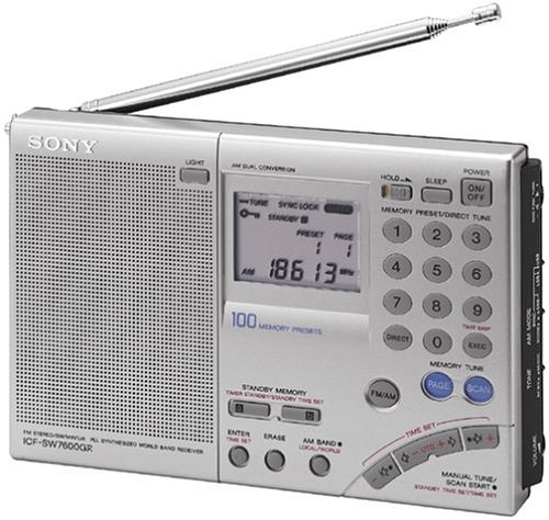
General information:
Good things:
Problems:
Sony XDR-S40DBP
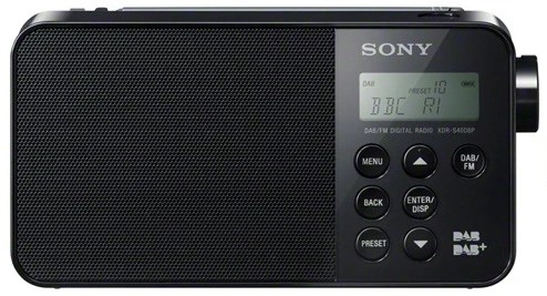
General information:
Good things:
Problems:
Sony XDR-S41D

General information:
Good things:
Problems:
Technics
Technics is a Japanese brand name of the Panasonic Corporation for audio equipment. Since 1965 under the brand name, Panasonic has produced a variety of hi-fi products, such as turntables, amplifiers, receivers, tape decks, CD players and speakers for sale in various countries. It was conceived for a line of high-end audio equipment to compete against brands such as Nakamichi.
Technics SA-5370
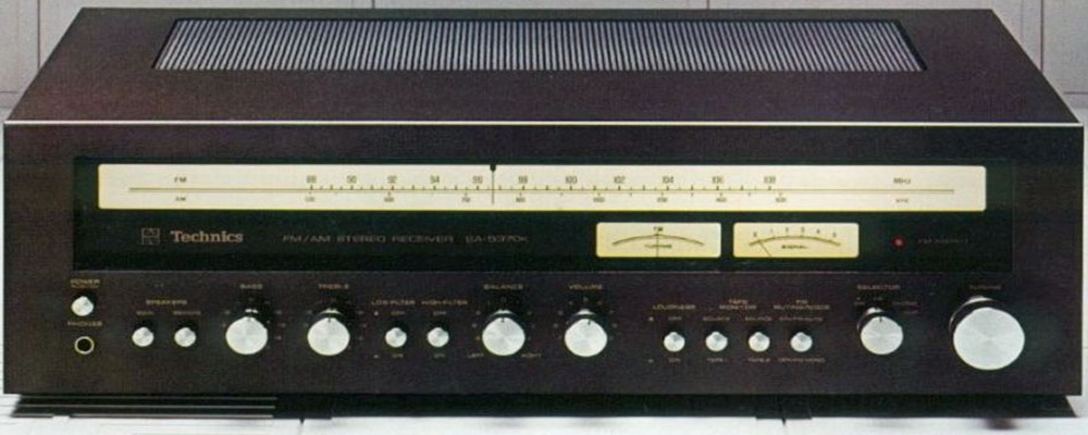
General information:
Good things:
Problematic things:
Its sensibility outperforms some tuner with better specifications.
In some forums are mentioned, its sound is better than Marantz's 2220 and Technics SA-300 & SA-400. Both Technics receivers has almost same schematic with SA-5370, and the tuner part are also same with ST-8080. It retailed for about $330 back in 1977, which in today's dollars is roughly $1100!
Technics SA-80
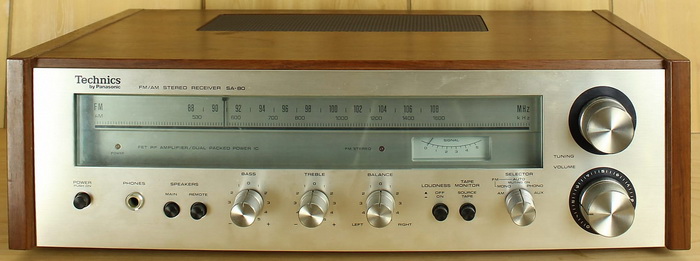
General information:
Good things:
Problematic things:
All used ceramic filter are with orange mark - means their frequency is 10.73MHz.
Modifications:
Power line: C302, C701, C702 to 470uF/35V; CC413, C704 to 1000uF/35V; C310 to 270uF/25V; C619 390uF/35V
Signal: C211 1uF/63V ERO PP; C315 and C316 0.47uF/50V Wima; C411 and C412 1uF/63V ERO PP
Missing from the schematic: the power amplifier power line is fuse protected via 2 pcs of 3.15A fuse; the power switch are with 2 circuits, and both switches have in parallel 1-1 0.01uF/500V pop-up noise canceling capacitor. The power-transformer input voltage is selectable: 110-127-220-240 Vac. The pull-up resistor from the basis of output buffer transistors (Q301 and Q302) are missing from schematics and from PCB - later was soldered on the backside of PCB 1-1 27kohm resistor. The C309 on the schematic is 3.3uF/50V, in the receiver was mounted 4.7uF/50V.
Technics ST-Z1
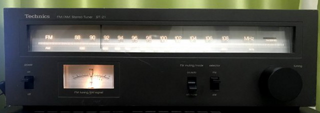
General information:
Good things:
Difficult, problematic items:
Other changes: R3 390 ohm, R4 33kohm, IC101 received 1kohm between pin4 and 6, and disconnected from R103 and CF102. R103 removed, and one 390 ohm resistor connected between pin 5 and 8 of IC101, and pin 8 to CF102. Pin 9 of IC101 connected to ground via 22nF MLCC COG. To the anode of D201 and ground was mounted 3.3uF/16V OSCON. R210 33kohm, C210 390uF/35V. R409/410 now are 560 ohms, R411/412 are 4.7kohm, C407/408 1uF/50V foil capacitors. IC103 pin 9 connected to ground via 0.1uF/100V, and pin 3 and 4 connected to ground via 10nF and 22nF. C502 560uF/35V, C503 470uF/35V, C504/505 820uF/25V. D501 and T501 B-C shorted with one-one 22nF. Audio power line received one puffer capacitor 390uF/35V.
After modification was necessary to increase R102 from 220 to 270, because local stations became distorted regarding 2nd amplification stage. Now is OK. Probably can be solved inserting one more ceramic filter after CF102, but must be identical with CF102 - but this depending from tuner to tuner, because I have another set from this, and there does not caused any problem this modification.
This tuners is same as the Technics ST-2700 FM/AM Stereo Tuner and similar to the Panasonic ST-2700L FM/MW/LW Stereo Tuner. Another similar Technics tuner is the ST-S1, which has LED signal level indicator and channel tunning indicator with related circuits. Technics ST-Z1L FM/MW/LW Stereo Tuner is the version with LW receiption capability.
Technics ST-G5
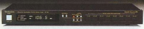
General information:
Good things:
Difficult, problematic items:
Technics ST-G3S
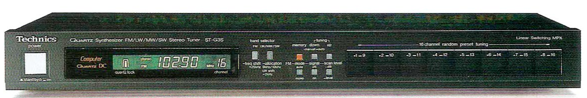
General information:
-
Shortwave bands:
Good things:
Difficult, problematic items:
Technics ST-G450
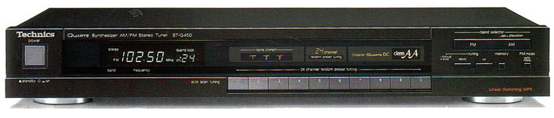
General information:
Good things:
Difficult, problematic items:
Modification (above changing all electrolytics):
Power line: C104 from 10uF to 47uF/63V, C106 & C901 from 470uF/6.3V to 1000uF/35V, C114 & C303 from 100uF/35V to 390uF/35V, IC 302 received a 100uH coil follower by a 390uF/35V puffer capacitor. C705 from 1000uF/25V to 2200uF/25V, C706 from 2200uF/25V to 3300uF/35V, C707 from 220uF/16V to 470uF/35V, C710 from 10uF/16V to 100uF/63V, C915 from 1000uF/6.3V to 2200uF/25V. At AC power input before received an EMI filter circuit formed by 2.2nF/2kV ceramic capacitor, the original filter coil, and after in parallel with primer of transformer one 1uF/275Vac pp foil capacitor. On both seconder coils received 1-1 220nF/275Vac PP capacitors. Because during usage the Q701 temperature was high, I inserted a heatsink on it.
Modifications in other circuits: at IC901 CE (pin 3) received a 100pF to ground and on AM_IN (pin 10) input line 3.3uH at the input. R102 was changed from 1.5kohms to 560 ohms, and the R103 from 330 ohms was changed into 560 ohms (like at GT550 & GT650). The pin 18 of IC102 now is connected to the power line via 100pF ceramic (like at G570).
Audio output: in case of the audio signal can be seen mostly DC connection, no capacitors - excepting the output of class AA circuit. If we take a look at the value of the output capacitor, seems very low. The output works in the best case (not considering the input resistance of the power amplifier and the impedance of output MPX filter, for simplicity) on 5.6Kohms + 2.7kohms resistor via 3.3uF, which means cannot be achieved the advertised 4Hz, as lower end of the audio band, just with a high loss. I put in this position (C315 and C316) 10uF/100V pp foil instead of 3.3uF/50V electrolytics (3x higher value!). Now the sound is in its right place with detailed bass and treble.
The new class A or called Class AA is a small trick, the output transistors conduct all time, just like the case of real class A amplifiers, for this reason, they never switch off, switching distortion is eliminated - but in reality, they work in class B. This is achieved with a special biasing of transistors: as the audio waveform begins to swing from positive to negative or vice versa, a very high-speed diode acts to raise the bias current slightly, the transistor remains in a low-level conducting state until the signal swing back again.
TechniSat
TechniSat is a German company founded in 1987 by Peter Lepper in Daun, Germany. Firstly, start to produce flat dishes with an edge length of 38 cm for receiving satellite DVB transmissions. In 1998 started producing the digital receiver, since 2005 HD ready LCD TVs, in 2011 started smart TV production, in 2012 DAB+ radios, and 2016 multiroom audio systems.
Viola 2 C IR
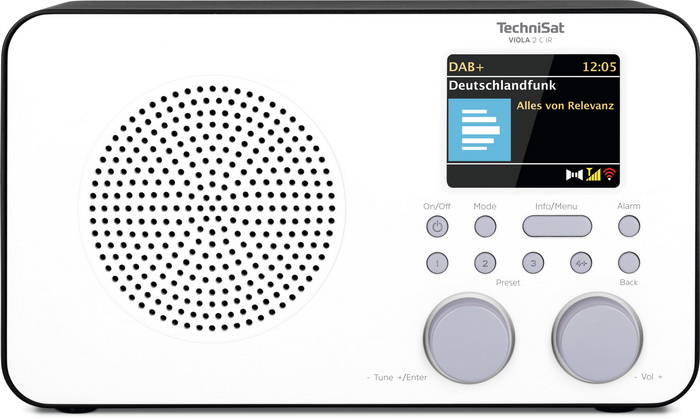
General information:
Good things:
Difficult, problematic items:
I think the battery capacity is insufficient for such a mobile radio. Since the interior of the chassis is nearly empty, there is room inside for an accumulator with a considerably higher capacity, such as 4000-5000mAh.
Its sound quality is awful. I made a complete closed speaker box by replacing the speaker with a wide-range 24 ohm type with the same dimensions and a heavier magnet, gluing it to the front panel (which was the same as the original one), and isolating the front panel from the chassis using silicone. The clarity and quality of the sound immediately improved. Later, I understood why the old speaker sounded so disoriented: when it was put into the front panel, glue was dripping between the speaker's chassis and diaphragm, preventing the latter from moving freely.
Its selectivity is fairly good, but, for instance, the sound of the Tivoli Audio Model One is far superior and cannot be compared (as well as being nearly 10 times more expensive).
Tecsun
Tecsun Co., Ltd. is a Chinese company founded in 1994 and headquartered in Dongguan, Guangdong. It designs and manufactures radios, from simple handheld AM/FM receivers to more sophisticated digital units with shortwave, longwave, airband, and SSB capability. Some of their products are rebranded and sold by Etón Corporation.
R-9701
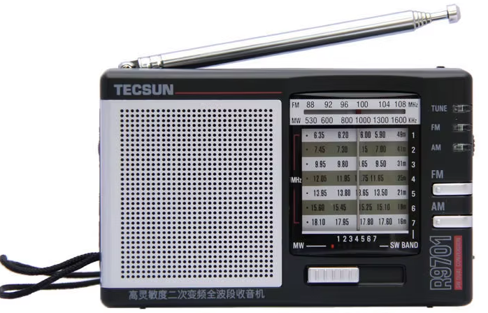
General information:
Good things:
Difficult, problematic items:
All SMD appear to have been manually soldered with manual insertion, rather than chip mounters, wave- (glued), or SMT soldering, as seen by their orientation and alignment on the PCB.
The radio IC, the CD2003GP is identical with the TA8164P, made by Toshiba, and is completely interchangeable with it.
There is a deviation from the schematic: C15 in the radio part is 33uF rather than 3.3uF, as can be seen on the schematic. C2, the audio decoupling capacitor, has a low value of just 0.1uF. It is advisable to increase it to 1uF (based on IC1 datasheet). Unfortunately this capacitor is an SMD ceramic type, and is no place on the PCB for a through hole one. In the audio section, the C29 (incorrectly labeled as C40 on the PCB, along with another capacitor that is indeed C40) is not mounted. This capacitor plays a crucial role in ripple rejection, achieving -34dB with a value of 100uF. This capacitor eliminate also the pop sound at switching on. After mounting, the noise appears to be undetectable. R34/L5 is not mounted; it is merely crossed by a wire. I maintain it as it was. Mounting an inductor can block the RF signal to the headphones (no effect), while a resistor can reduce the signal level at the headphones. However, since the speaker impedance is 16 ohms, this is not particularly significant. The amplifiers outputs does not contain any phase compensations, recommended by datasheet (ex 100 ohm + 0.1uF).
Value revision: the power amplifiers output capacitor, C41 is now 470uF/10V OSCON type (dry electrolyte) rather than the 220uF/10V that was originally mounted. On www.radiomuseum.com, the schematic diagram misidentifies C41 as 2200uF.
Telefunken
Telefunken was a German radio and television apparatus company, founded in Berlin in 1903, as a joint venture of Siemens & Halske and the Allgemeine Elektricitäts-Gesellschaft (AEG), creating Gesellschaft für drahtlose Telegraphie System Telefunken ("The Company for Wireless Telegraphy Ltd."). In 1941, Siemens transferred its Telefunken shares to AEG as part of the agreements known as the "Telefunken settlement". During the Second World War, Telefunken was a supplier of vacuum tubes, transmitters, and radio relay systems, and developed Funkmess facilities (later referred to as radar devices by the US Navy) and directional finders, as part of the German air defense against aerial bombing. During the war, manufacturing plants were shifted to and developed in the west of Germany or relocated. Thus, Telefunken, under AEG, turned into a smaller subsidiary, with the three divisions realigning and data processing technology, elements as well as broadcast, television, and phono. Telefunken was also the originator of the FM radio broadcast system. In 1967, Telefunken was merged with AEG, which was then renamed to AEG-Telefunken. When AEG was bought by Daimler in 1985, "Telefunken" was dropped from the company name. In 1995, Telefunken was sold to Tech Sym Corporation (owners of Continental Electronics Corporation of Dallas). However, Telefunken remained a German company. In August 2006, it was acquired by the Turkish company Profilo Telra, one of the largest European manufacturers of TV devices, with brand-owner Telefunken Licenses GmbH granting a license for the Telefunken trademark rights and producing televisions under that name.
Telefunken 076WK
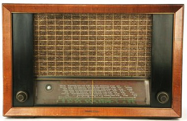
General information:
Telefunken RT300
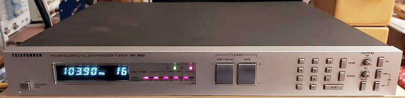
General information:
Good things:
Difficult, problematic items:
Telefunken in this tuner used the highest technology of that era: MOS controller system with EPROM, 40(!) random preset memory (no battery or supercapacitor required to keep stored stations), remote control, auto searching up and down, 10 level signal meter, etc. The digital part was made with mixed technology: SMD components used with through-hole components (glued SMD, dried in reflow, after mounting the TH, and finaly soldered via wave soldering machine). Despite 10kHz tunning steps on FM, the station transmitted frequency is detected very precisely, with no deviation after more than 40 years!
The overloading of AM input is protected by a photoresistor, which is controlled via a bulb connected to AM demodulator signal level. Also, a bulb is used to control the input current of the the digital section before the voltage regulator. Simple and effective solutions! The power of the digital part is made using an intermediate transformer driven with 17Vac from the main transformer (no PWM switching power supply, means less noise).
Components: were used very good ones. Most of the capacitors have an acceptable loss (2.5%, and their ESR are still very low) - except in the digital part. There most of capacitors were already dried, isolations hardened or capacitor leg died by the electrolyte. All electrolyte capacitors were changed to new ones (electrolyte, solid electrolyte, tantalum, or foil type. The rectifier (B30C350KP - is a selenium bridge, nowadays with a high defect ratio regarding their limited service-life, appr. 60000 hrs, progressive increase in forward resistance, increasing forward voltage drop, and reducing the rectifier's efficiency) in radio section must be changed immediately at first repair. In several related forums are recommended, because can deteriorate both controllers. In my set instead of 2 signal level drivers (U244B and U254B) is used the TFK D-620P LED bar component with 4 pins (Vp, In, and 2 GND) which has the drivers incorporated, made by Telefunken (probably which contains the before mentioned ICs), but the assumed U254B does not work, must be replaced the whole component (for this reason can be seen on the picture just 5 lighting LEDs, not 10).
For further improvement: the places of ceramic filters on PCB were made for old type filters with 4 pins and also for new type with 3 pins, and from 3 pin-types can be used 2-2 pcs on series connection. The current one after tuner is SFE10.7MX (BW +-250kHz, insertion loss 12dB, low distortion) with 3 pins, and after IF amplifier is SFJ10.7MB (BW +-190kHz, insertion loss 8.5dB) with 4 pins, both with Murata type with blue body and orange dots (center frequency is 10.73MHz). Verdict: is a very underestimated tuner, cheap on second market (30-40?), and very sensible with a good sound.
Telefunken HT850
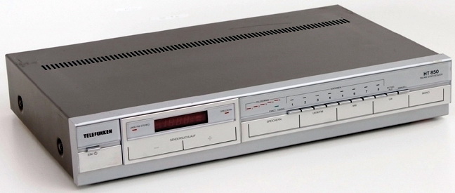
General information:
Good things:
Difficult, problematic items:
The internal part is almost the same as the next generation model, HT870: the AGC's RC part is different, has 2 IF amplifiers stage, one with TA7060, and one with one transistor, the oscillator output has a buffer made with FET, the MPX circuit output has a buffer operational amplifier (NJM4558DD).
All 3 10.7MHz ceramic filters are 10.7S type with red dot on top right side.
Modification made based on HT870, mostly for noise reduction and AM signal level improving: in tunning circuit was inserted 3 pcs of 2.2uH coils before R114, R129 and the triplet of R101-R109-R110, C104 received 0.47uF in parallel, R202 and R236 removed, R206 and R207 were interchanged, and in parallel with R207 position was mounted one 560pF, C304 now is 2.2nF, C302 became 47uF/35V. The FM antenna input now is connected with AM antenna socket via 2.2uH in L201 position, and the original coil from this is incerted between AM socket and AM tuner input (C201).
Other changes: C306 10000uF/16V as memory capacitor. Now after half year still the stored memory setting works! The power line of IC302, pin 41 and 42 received the power through one 100uH coil. C227 now is 100uF + 22nF, C221 became 100uF. C164 was decreased to 0.22uF. All audio capacitors, C166, C167, C169 and C170 now are 10uF/50V Yageo type. C159 and C171 now is 470uF. Changes in the power supply: C501 now is 3300uF/25V, C504 and C507 is 470uF/50V, C510 now is 330uF/35V, and C511 270uF/16V.
The voltage stabilizer IC (7815) was mounted in the back plate to transfer the heat outside from tuner - without this, the IC became very hot after several hours of listening. All electrolytics were changed.
Status: after purchasing it (was 20$ in the middle of 2022), the reception frequency on FM was shifted to -50kHz - so the stereo signal was weak. After changing the capacitors and finalizing the above-presented improvements, this deviation became smaller but was between the exact transmitted frequency (probably -25kHz), which means became worst, because in both positions the stereo signal comes with hum. In such cases can be adjusted the FM IF circuit coils: with IF101 you can set the center (please be careful, just a very-very light movement can be made in CCW direction), and after that should be adjusted the IF103 for clarity/minimal distortion, a bit more than in case of IF102. This process should be repeated till the sound is perfect. I recommend selecting a weak station for adjustment, with stereo almost receptable.
The sound is quite good after modification. Now has seems more clear in the whole audio spectrum.
Telefunken HT660
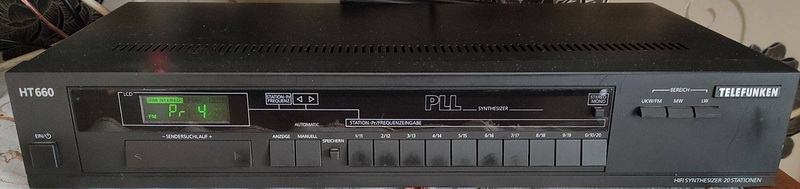
General information:
Good things:
Difficult, problematic items:
The internal part is almost the same as the flagship model, HT870: the AGC's RC part is different, has 2 IF amplifiers (at HT660 the last 2 ceramic filters are connected in series, at HT870 is one transistor amplifier between them), the oscillator output has a buffer made with FET, the MPX circuit output has lightly different RC filters and in signal path has higher capacitors, the controller and surrounding circuit is different.
All 3 pcs of 10.7MHz ceramic filters are 10.7S type with red dot on top right side.
Between schematic and real tuner are some differences: at FM input is no transformer, but has a ceramic FM band filter, the C132 1uF/50V was not mounted, C601 instead 1uF/50V is 47uF/16V, IC301 NJM4660D not mounted (the automatic search is solved with transistors)
Modification made based on HT870: in parallel with R125 was mounted 1uF/63V PP, C132 mounted as on schematic, C147, C153L and C153R changed to 4.7uF/63V PP, C148L and C148R changed from 1000pF to 820pF, R148L and R148L changed from 47k to 51k.
I think this tuner was made in South Korea: all electrolytic capacitors were SamHwa SA type, the transformer was made by Han Young Electronics Co., the design of PCB, used ICs are Far-East style.
The voltage stabilizer IC (7815) was mounted in the back plate to transfer the heat outside from tuner, and received an EMI filter before transformer (0.47uF-2x8.2mH-0.47uF). All electrolytics were changed.
The sound is quite good after modification. Now has equilibrated bass, clear trebles. The stereo image is good. From specification comes the stereo signal detection should be at 35uV signal level - I think, compared to other tuners, is at 20uV level. The transition from mono to stereo is quite smooth. As a garage tuner is a more than perfect choice, consider attaching for it a good antenna.
Telefunken HT990 RDS

General information:
Good things:
Difficult, problematic items:
The internal part of this tuner is nearly identical to the model TS2030 of SABA (which was at that time part of Thomson Group), as is the design, including the PCB style, and functional units component notation. The RDS module is completely identical in terms of schematic and component values; the only difference is the PCB: on the Telefunken, the filters are on the radio board, whereas on the SABA model, they are entirely on the RDS PCB.
As I previously stated, power line design is quite "German" - one filter capacitor near the rectification, and the units rarely employ buffer capacitors, only noise suppression filters (tens of hundreds of nanoFarads). The bass became more live after significantly raising the values of the local filtering capacitors. The same holds true for audio signal coupling capacitors: their values were carefully calculated for audio bandwidth, yet raising their value improves the musical experience.
Modifications (just component values): Audio: CB01, 02, 07 and 08 to 22uF bipolar, Fine Gold, Nichicon. Power lines: added decoupling capacitor in parallel with CP03 and 08, 100nF/50V MLCC, CP04 increased to 10uF/25V Ta (decreasing the noise of voltage regulator), CB11 was completely out of order - nominal values should be 10uF/16V, in reality measured was 31uF with 3.4 ohm ESR and 50% loss. Now it value is 22uF/25V. CD01 changed to 220uF/16V, CH32 to 270uF/16V dry electrolyt type, CT10 100uF/16V dry electrolyte type, CH22 same value, but Ta type.
I couldn't find the user/operation handbook on the web. Its sound is now highly balanced. The RDS requires a certain signal strength (a little higher than stereo), and by scrolling, the entire station name will be displayed on four characters. The radio text is not available. The tuner includes remote control capability, however this was not tested because I purchased it without RC.
Tento
Elektrit Radiotechnical Society was the largest privately owned company in Wilno, Second Republic of Poland (now Vilnius, Lithuania) (1925-39). With over 1100 workers, the society produced approximately 50 thousand radio receivers annually. Elektrit proved to be a very successful company and soon became a leading radio manufacturer in Poland. Following the Soviet invasion of Poland in 1939, Wilno was occupied by the Soviet Union and the company was nationalized. In 1940 the factory was hastily dismantled and transported to Minsk, where the "Vyacheslav Molotov" Radio Factory was set up. After the war the plant was renamed Minsk Radio and Television Association "Horizont". At the beginning produced "Minsk" radio receivers, being copies of Polish pre-war models but with Soviet tube set, later start to make their own designed sets using Russian semiconductors. The factory was renamed Tento (date unknown). Most famous radio receivers of this factory from 1980's: VEF 206 and 242, Okean 214, Sokol 304, Selena B211 (210, 212) and B216 (215, 217).
Selena B-211
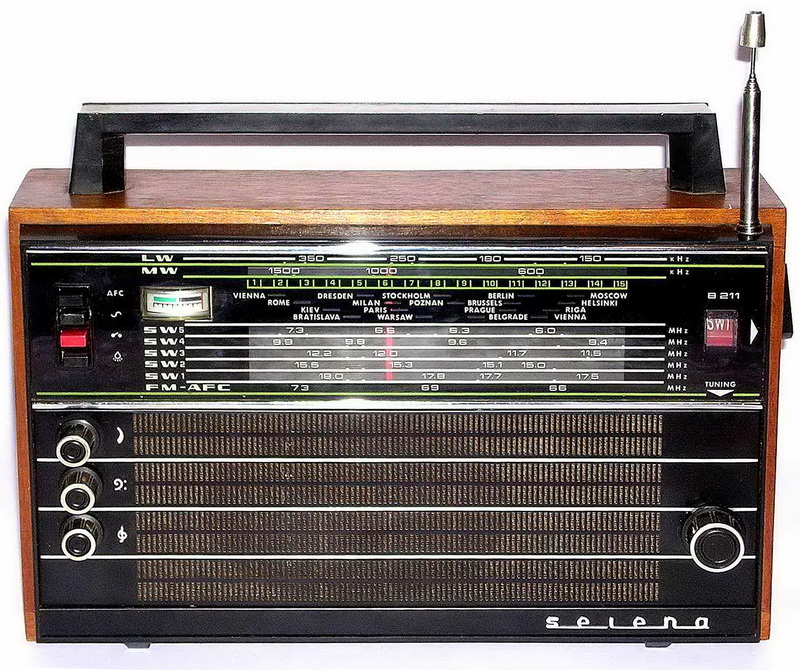
The scale and the signal meter are luminated via 2 bulbs of 2.5V/65mA. Has audio output for tape recorder: 6mV/10kohm, treble (6.5kHz) -15...+10dB and bass (200Hz) +-10dB adjustment, AFC for FM, and switch to disconnect the AC power (not same with the Power On).
General information:
All electrolytics must be changed immediately. All produced before 1989 made for consumer electronics are dried. Has a very pleasant and warm sound via its own speaker, and with very clear sound on AM!
Spidola/VEF 242
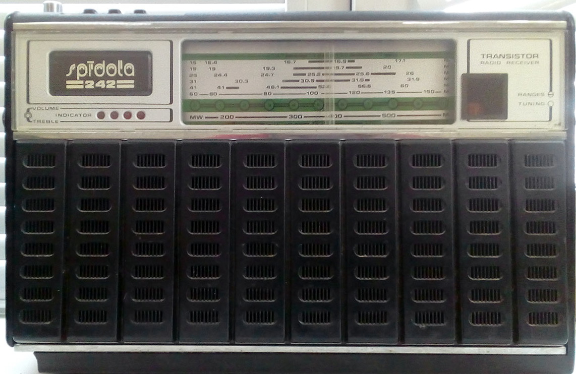
Two 2.5V/65mA bulbs are used to illuminate the scale and the band mark. Four LED bars come together to form the signal level indication. Features a tape recorder audio output with adjustable bass (200Hz) and treble (6.5kHz) levels of -15...+10dB and 6mV/10kohm.
General information:
Good things:
Difficult, problematic items:
Replace all electrolytics right away, just like you would with a Russian radio. Has a decent AM reception on a table radio. The radio portion was designed in 1979 and is composed entirely of Ge transistors, including the output stage. The audio amplifier also includes two transformers: one for the signal-inversion and another for impedance matching.
Selena B-216
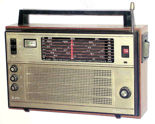
The scale for Russian radios is reversed, which means that the lower frequencies are on the right side and the higher frequencies are on the left.
The scale and the signal meter are luminated via 2 bulbs of 2.5V/65mA (difficult to be found). Has audio output for tape recorder: 6mV/10kohm, treble (6.5kHz) -15...+10dB and bass (200Hz) +-10dB adjustment. Switches: AFC for FM, and switch to disconnect the AC power (not same with the Power On), and switch to turn off the lights.
The construction of the case consists of a plastic front panel and a plastic back panel, together with a wooden side sandwiched at the centre.
General information:
The audio amplifier is made via K174YH7, which is pin compatible with TBA810 common audio amplifier IC.
The receiver has a built-in power supply with a round socket of the USSR standard, difficult to be found power cable for it.
All electrolytic capacitors must be replaced immediately; capacitors manufactured before 1989 for consumer electronics have dried out (however, the capacitors used in export models are still much better than the electrolytic capacitors used in domestic products, i.e., those intended for internal consumption in the former Soviet Union).
Has a very pleasant and warm sound via its own speaker, and with very clear sound on AM!
Selena B-215

The radio has 2 main PCBs: the radio unit (the whole AM, and the FM without the tuner), and the audio part, which includes also the power supply.
General information: same as B216, but FM with 87.5-108MHz
Modifications: Like in case of any Russian radio, immediately all electrolitic capacitosr must be changed.The power supply is very simple, as in the case of VEF radios or SelenaB211, but here has a zener diode, which means the circuit acts as a real voltage regulator, not just as a capacitor multiplier - this means the radio will be powered exactly from 9Vdc, and the regulator is a darlington. Unfortunately, the guys from PCB design do a poor job, even when considering the ground loops. As a result, if the radio is used from a power line, it produces a significant amount of ground noise/brum, which is independent of the value of the filtering capacitor value and other components. Solution: remove the anodes of rectifier diodes VD6 and VD7 off the PCB and link them together, then connect with a wire to the negative pole of C21 on the PCB. In addition, I increased the C21 capacity from 470uF to 3300uF/25V and added a 0.1uF/50V MLCC in parallel with it. In parallel with C20 (47nF), I soldered a 100uF/16V solid electrolyte capacitor to the solder side of the PCB. C10 was replaced, and an additional 0.1uF/50V MLCC was added in parallel. With this modification the ground noise is very minimal. Another recommendation is to utilize external power, which eliminates the noisy internal transformer, and I do so. An external low voltage connector can be mounted between the tape audio output and the high voltage power socket. Already is a hole on the plastic part of the chassis that is excellent for this low voltage socket, and you should make a hole for it on the back plastic plate. The connector is connected to the primary filtering capacitor (C21) pins soldering side via a single 1N4002 diode and wire. I used a Philips wall plug with 230Vac, 11W and 9Vac output, but inside it was feasible to mount a 4uF/100V MLCC in parallel with the secondary windings, followed by a rectifier, 1000uF/16V+0.1uF/50V MLCC, 2x80uH EMI coil, 1000uF/16V+4uF/100V MLCC, and 2x20mH EMI coil 4uF/100V MLCC, all connected in this order to the output cable. Using this external power supply, there is no noise on the LW/MW/SW bands from power lines. Some mod pages advocate changing the original rectifier diodes with 1N4001; I omit this recommendation, because now they are not used regading the external wall plug.
The audio portion has a decent bauffing sound, but on this radio, I tried to tweak it a little so that it would be more detailed and clear when receiving FM. After reviewing the service manual, I advised increasing the input capacitors (C1 and C3) from 2.2uF to 4.7uF, but when I removed them, I discovered that the Russian components were originally 5uF/12V. Now I replaced them with 4.7uF/63V Rifa foil capacitors. C2 was also raised from 150nF to 470nF/63V foil. C9 is now a 220nF foil, C7 is a 100uF/35V capacitor, and C8 is 470pF.
AFter modification has as a very pleasant and warm sound, detailed trebles via its own speaker, and with very clear middles, not just on FM, also on AM. Is the best sounding portable table radio from my collection.
VEF-214
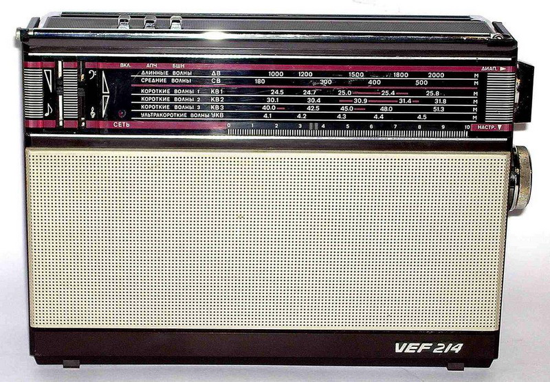
Includes just six selectable bands: three shortwave bands, LW, MW, and FM. The sensitivity is especially noteworthy in relation to MW. Control the tone and volume with loudness (this feature cannot be turned off). The scale does not have any illumination and is missing a signal meter. At the top, you will find three controls: AC, AGC, and muting. It features a 6mV/10kohm audio output suitable for the tape recorder.
General information:
I bought my set for $8 because it was defective, and while checking the defect reason, pressing the PCB caused the radio to wake up and begin to emit sound. The main defect was caused by oxidized component legs; later, I discovered the second problem, dry electrolytic capacitors. I resoldered the critical areas of the entire PCB and replaced all electrolytics without delay. I found some with 26pF and 276pF instead of 10uF, but nearly every electrolytic capacitor exhibits more than 6% leakage and over 7 ohm ESR.
Changes: at first, I considered the VEF-216 schematic as well: the main board/PCB in my radio resembles the VEF-216 model, rather than the one presented in the VEF-214 service manual. This was great news because Tento made several improvements to this model, and the PCB design became more correct. It appears that at the time, the improvements were applied to all production models at the VEF factory, either intentionally or due to a lack of materials (we are now approaching the end of the Soviet era). For example, some improvements seen on VEF-317, the latest radio, can be seen implemented already here in this radio, and not just as a temporary solution, but they were applied including the PCB's design: for example, both transistors (VT12 and VT13) in differential stage of audio amplifier have in collector resistors (newly appeared the R60, also 4.7kohm). Same situation I meet in case of components values: R43 15kohm, R45 4.7kohm. The fact that there is less background noise when compared to the VEF-206 and VEF-222 receivers is most likely due to improvements. Modifications: C2 on the power supply was changed to 3300uF/25V, and C50 is now 1000uF/25V in parallel with a 4.7uF/100V MLCC. C53 at the output is now 820uF/25V, C28 is 100uF/16V, and the C5 from the switch and volume panel has an additional 56nF foil capacitor in parallel with the original 100nF. The remaining electrolytics were replaced with new ones and the same values.
Compared to VEF-317 I meet other modifications: R15 560ohm, R17 2.2kohm - both implemented, but during listening did not recognized improvement in sound or sensibility. A significant but not tested difference: R6 30kohm, R22 0ohm/shorted, L2 connected to V+ via 1kohm, and their connection grounded via 33nF ceramic capacitor.
This set lacks the practicality of the Selena B216, B211, or VEF206, offering only a few SW bands.
VEF-222
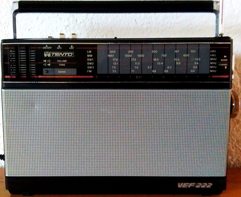
Contains only six selectable bands: three shortwave bands, LW, MW, and FM. Its sensitivity is particularly remarkable with regard to MW. Tone control and volume with loudness (cannot be deactivated). The scale lacks illumination and is devoid of a signal meter. There are three controls on the top: AC, AGC, and muting. Has 6mV/10kohm audio output for the tape recorder.
General information:
Immediately replace all electrolytics (I discovered some with 143pF rather than 1uF, a 100uF in the power regulator with 41.4uF/3.6 ohm ESR/9.2% loss, and a 10uF that was entirely dry, whereas the 22uF had 49.99uF/4.4 ohm ESR and 6.4% loss). Everything manufactured for consumer electronics prior to 1989 is desiccated.
Modifications: Initially, I also contemplated the VEF-317 schematic: I inserted a 1k resistor between L2C14 and +5V, and a 33nF capacitance was connected to ground between this resistor and L2C14. The collector and emitter resistors of VT4 were modified to values of 0 and 1kOhm, respectively. Driver prior to tape output: a 33nF capacitor was connected in parallel with R73, and the value of R76 was altered to 3k in order to produce a signal that could be utilized at the tape output. C4 is now composed of a 270uF/16V solid electrolyte. R17 was reduced to 2.2k, C28 is now also 270uF/16V solid electrolyte (50uF on the schematic, 22uF on the device), C44 should be 1uF (originally was 0.1uF ceramic), and C6 received 47nF in parallel with it. The 2000uF/16V C2 was substituted with a 3300uF/25V variant.
The schematic for the FM demodulator board differs from the datasheet of IC K174XA6 (which may be the same as TDA1047): C14 should be 2uF rather than 1uF, C8 should be 50uF rather than 1uF, and C7 should be 5uF rather than 2uF. C9 is fine at 10uF. Mounted C8 was 10uF and C7 was 4.7uF, which is close to the values listed on the datasheet.
This set is not as sensible as the Selena B216, B211 or VEF206.
Terta
The history of the factory dates back to 1876 as a Railway Fittings and Electrotechnical Machinery Factory (Vasúti szerelvény és elektrotechnikai gépgyár) at Budapest, Hungary. In 1894 it became a domestic division of the company A. G. vormals J. Berliner, and since 1903 it has been called the Telephone Factory (Telefongyár). The factory was little known to the wider public but was always at the forefront of the Hungarian communications industry. In 1918, it produced the first transceiver with an electron tube. Until the end of World War II, it was owned by the German Telefunken. After the nationalization in 1949, the company was "asked" to manufacture sound amplifiers and sound film projectors, railway safety, and signaling equipment, telephone and telegraph equipment, and a telephone exchange. In the second half of the 1950s, very high-quality tape recorders were produced for public use, based on their development. Among the first to be produced were tubular and then transistorized pocket radios and portable transistorized tape players. In 1991, during the privatization of state-owned industry, Siemens acquired Telefongyár Rt., and Siemens Telefongyár Kft. was created. In 2003, Siemens Telefongyár Kft., Siemens Investor Kft., and Siemens Rt. were legally merged, thus the name Telefongyár itself disappeared.
Orionette 1004
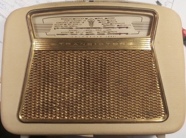
General information:
With more than 65 years, the radio is perfectly tuned in, and its reception is still good after all these years. The tuning is fine and quite accurate for the scale. The large speaker in the wooden box produces a pleasant sound, with a good volume (at the time, a small tube super couldn't do more).
Was necessary to change all electrolytic capacitors.
The transistor used as a diode has the function of thermal stability of the output audio amplifier and was used from the defective transistors from the manufacturing process.
The P14 transistor was among the first transistor models manufactured by Tungsram, under a Russian license - for this reason, this transistor looks like Russian transistors. At that time the transistors manufactured by Tungsram does not work above 1MHz, which means the manufacturer ordered high frequency transistors from Japan (2SA15, 2SA12) or from USA (2N219, 2N218) - used in the radio part.
The small coil attached to the back cover via a socket is the external antenna connection, which inductively (with a closed cover) will be very close to the inside ferrite rod, transferring the signal to the input RF circuit of the radio.
The decoration band around the radio is detachable and turns into a radio that can be hung on the shoulder.
Versions: with one transistor preamplifier between the radio parts and the power amplifier stage, later this was modified by combining this preamplifier with the first stage of the amplifier. In the early versions, the speaker was connected between the connection of 2 serially connected batteries, to reduce consumption.
Tivoli Audio
Tivoli Audio is an American manufacturing company notable for producing a line of up-market tabletop radios and related audio products. It was founded in 2000 by Tom DeVesto in collaboration with Henry Kloss, who perceived a gap in the consumer audio market for a high-quality, well designed and affordable AM/FM radio in congested urban locations, while maintaining the ability to pick out distant or low power stations. Tivoli Audio is best known for its Model One Radio. By 2006, Tivoli Audio had become a global luxury brand, selling in over 30 countries and gaining recognition in the audio and design world.
Tivoli Audio Model One
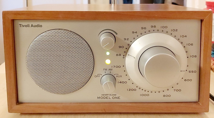
Antennas are internal but a rear jack allows for an external FM aerial where required (an FM telescopic aerial is included). The antenna signal is captured by a discrete-component FM tuner with GaAs MES-FET mixer, which gives low noise, high sensitivity even with closely spaced stations.
General information:
Good things:
Difficult, problematic items:
Tivoli Audio Model Three
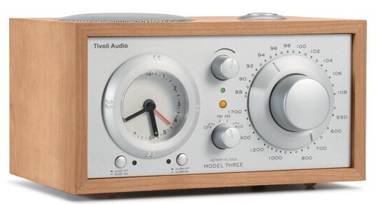
General information:
Good things:
Difficult, problematic items:
On a few portals can be seen comparisons between Sangean WR-1 and WR11 with Tivoli Audio Model One, Model Two, and Model Three - and the winners are the Sangean radios, which outperform the Tivoli Audio receivers, and are much cheaper.
Uher
UHER Werke München KG, commonly abbreviated to UHER, was an electronics company in München (Germany) that was specialized in the development and manufacture of (portable) open-reel tape recorders. The company was established in 1952 and was sold in 1974. Since digital equipment has become widespread, these older analogue recording machines are no longer produced. Two parts of the Uher company still exist; one which has focused on informatics, and ATIS Uher focused on IT security. Currently the brand are owned and licensed by Assmann Electronics of Bad Homburg.
Uher EG-750
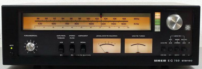
General information:
Good things:
Difficult, problematic items:
I found just one deviation from the schematic: the power of the 333Hz signal generator has an extra 47uF/25V in the supply part.
Parts modified: C320 22uF and C303 10uF connected in series changed with only one 10uF pp foil capacitor. C602L and C602R were replaced with 1uF/63V pp, C603L and C603R were replaced with 4.7uF/63V pp.
In power part: C803 replaced with 2200uF/35V, C804 with 470uF/35V, C807 with 1000uF/35V, C124, C169 with 270uF/16V, C318 with 470uF/35V.
Unitra
UNITRA was the Association of Polish consumer electronics manufacturers (more than 60), and was established in 1961 and lasted in its original structure until 1989. After the systemic transformation, consumer products under the Unitra brand name reappeared on the market. Electronic equipment manufactured under the common Unitra brand measured up in quality to comparable equipment produced in the entire Western Europe. The Unitra equipment earned a high reputation thanks to the quality and reliability of the manufactured products. Among other things, the Association ran its own R&D department and a common commercial bureau. Due to its long-lasting tradition and user confidence the brand is recognizable to date and is prized for the high quality and durability of its products. As a result of the political transformation in 1989, manufacturers' associations were disbanded. Individual companies became independent and continued their activity with varying degrees of success.
Some important associated manufacturers: CEMI - semiconductor devices, DIORA - HiFi sets, FONICA - Turntables, stereo amplifiers, TONSIL - loudspeakers boxes, ZRK - cassette decks, stereo receivers. In general, Unitra Diora was an East European manufacturer and produced relatively good FM tuners before 1989 mostly for communist countries.
Unitra AS630
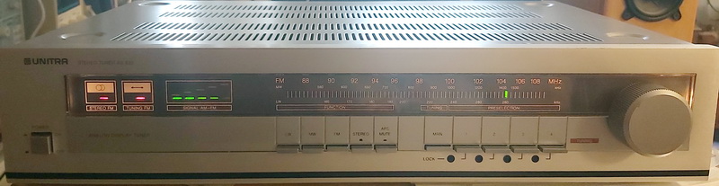
General information:
I purchase it after AS631 model (without tunning knob, and as you can see, I replaced it. The radio part is completely same.
The sensibility is very good in comparison with specification, the sound is very pleasant, detailed, with rich bass and beautiful treble (after modification).
This tuner frontend is just with BJT, which has a higher background noise compared with MOSFET, the AM section is made with A244D (TCA440T).
The tunning indicator was upgraded (same as in AS 641) - now is amplified with 2 transistors, and has more exact feedback.
Modifications:
Power line: after R216 the power of frontend received a 100uF/16V dry cap (in not mounted but marked C210 position), C200 is 470uF/35V, C222 received in parallel 10uF/50V, C233 270uF/16V dry cap, C252 100uF/16V dry cap, C276 received 1000uF/25V in parallel, C281 received 10uF/50V in parallel, C282 470uF/63V, and instead of R267 was mounted 3.3uH coil. Now cannot be heard any noise generated by LED lamps, laptop or mobile wall-plug or switching power supplies during listening AM stations.
Other changes: C242, C252 and C262 changed to 2.2uF/100V foil cap, C269 and C274 changed to 1uF/63V foil cap. As previously was mentioned, in tunning indicator circuit was inserted the T504 BC238 and R510 12kohm, and R512 was changed from 22kOhm to 47kohm.
As tuner, just one additional modification I recommend to be made: the audio buffer, like in AS 641 model.
Unitra AS631
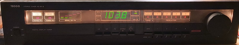
General information:
I purchase it specially to test it, and at the beginning, I did not expect too much from this, because I experienced the quality in post-communist countries were far from my expectation, but all goods sold to capitalist countries were well made - but almost from same components. The technology and the circuits used in this tuner seems to come from the end of 70'/beginning of 80', including the digital scale.
The sensibility is very good in comparison with specification, the sound is very pleasant, detailed, with rich bass and beautiful treble.
This tuner has a newer version, called AS 641 - the radio circuit is almost the same excepting the first stage, which uses MOSFET with AFC, the AM section is made with UL1203 (TCA440T), and at the audio output, after 2 LC filters has an output buffer on a separate PCB attached to the RCA connector. Seems a very elegant solution, and that was reproduced by me and inserted in my set. The digital part of AS 641 is completely different: use LB3500 as prescaller and LC7266 as controller, counter and display driver, and use 8 presets made with SAS580-SAS590 ICs.
Videoton
The legal predecessor of VIDEOTON was founded in 1938 under the name of Vadásztöltény Csappantyú, Gyutacs és Fémárugyár Rt (translated could be Hunter's Cartridge, Clapper, Lighter and Metal Factory Co.). After the World War II. the company was rebuilt and owned by the state between 1955-1991. It developed, produced, and sold Videoton branded consumer-, computer- and defense (military) electronics. From 1981 the company was called VIDEOTON Electronics. It has earned a serious reputation for its portable- and desktop radios, TV sets, speakers, and later Hi-Fi systems. After the political changes in the early 90s - especially due to the canceled orders of the East-European market - the company got into a difficult situation, therefore its liquidation started in 1991. The current shareholders and Hungarian Credit Bank and Euroinvest Ltd. acquired the company's assets in a public tender, and they rename the company Videoton Holding Rt. The company now is the 25th EMS (electronic manufacturing service) company in worldwide rank.
Videoton RT 7300S
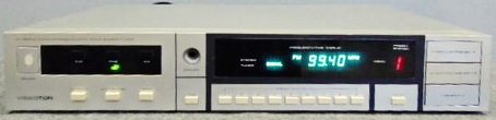
General information:
Good things:
Difficult, problematic items:
The technology and the circuits used to come from the beginning of 80', including the digital scale. Most of the electrolytic capacitors are axial TH type regarding modular system and low profile of tuner - which are difficult to purchase. To be noted: almost each ICs are powered via LC filters, which decreases the noise transmitted via power lines. Has an output buffer (TL082), and the best one: has a built in headphone amplifier, you do not need to use a separate one. The sensibility is very good in comparison with specification, the sound is very pleasant, and detailed, similar to the Pioneer FX90, but with just a bit less dynamic, and also with a less bass - but very close.
Modifications: all electrolytics changed, and also all through-hole 100nF ceramic capacitors.
Changes:
In conclusion, while it is a decent tuner, it may experience instability at times due to subpar connectors. AM performance is exceptional, surpassing that of the older Marantz receivers, while FM2 (CCIR) is nearly comparable to the Pioneer FX90. The built-in headphone amplifier is an advantage; there is no necessity to switch on additional equipment in order to listen to it.
If the tuner is properly aligned and refurbished (recapped), it can function as the primary tuner in a music center or independently. It is typically utilized in close proximity to the preferred reading location of a study desk using headphones.
WEGA
(Sony)
WEGA, was founded as Wuerttembergische Radio-Gesellschaft mbH in Stuttgart, Germany in the year 1923. Sony purchased WEGA in 1975, which means after acquisition several models were built under Sony design. Wega products were then known throughout Europe for stylish and high-quality stereo equipment, designed by Hartmut Esslinger, amongst others. Sony used the Wega name for different products (Trinitron flat screen or LCDs TV sets). Defunct at 2005.
WEGA JPS352 SE T
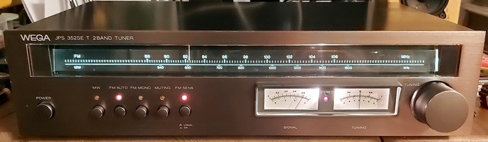
General information:
Additionally received an AC filter. All electrolytic capacitors changed. IC power pin grounded with 1uF/35V X7R MLCC, also the C125 received in parallel a 47pF/50V C0G MLCC (recommended by user manual of AN7000), and in the audio output stage a puffer capacitor (22uF/63V).
In series with scale light bulbs received a 20ohm NTC resistor (to protect them, because the tuner was built for 220VAC, and now in my home, I can measure 238VAC).
The signal from FM antenna input socket goes into the L101 impedance adjusting transformer, which has an output for a 300-ohm antenna connection - can be used if somebody has such an antenna.
This radio on several portals are mentioned as a Sony clone.
WEGA T120
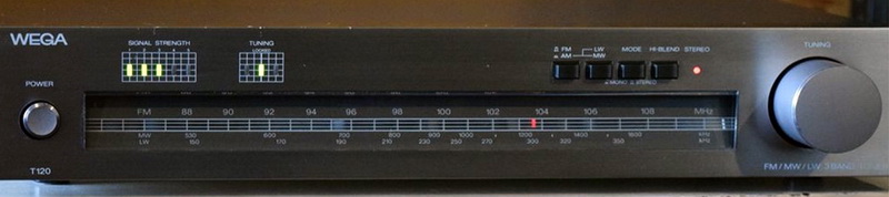
General information:
Differences compared to service manual: not mounted C602 and C603 from the AFC circuit (both 0.47uF), and the value of C204 instead of 1uF is 4.7uF/25V.
All electrolytic capacitors were changed. ICs buffer capacitors were replaced with 470uF/35V (C212, C301, and C422).
In power supply the C803 changed to 2200uF/25V, C805 to 470uF/35V, C804 and C808 to 390uF/35V, C806 to 100uF/63V.
In the audio part, I used just PP capacitors. Just the output capacitors value was changed/increased from 0.47uF to 1uF (C313 and C363), because the bass section does not need any changes. The set has a very warm sound reach in the bass section.
After the power switch, I mounted an EMI filter before power transformers primary coil (2.2nF+2x7.6mH+0.47uF), which was necessary to be shielded.
Overall, is a good tuner with high sensibility on FM, good "acute servo lock", and is very listenable! The AM section is not so good, the sound is not distorted, but the background noise is high.
XHData
Is very difficult to determine the name of original manufacturer, because can be seen as made by Radiwow, or by Sihuadon - but we know, the factory is located in or near to Shenzhen city, in China. All 3 brands appear under xhdata.com.cn webpage. Sihuandon D808 is exactly same as XHdata D808, just in black color with orange backlight. Raiwow R108 is completely same with Sihuadon R108. The Radiomuseum.org mention is manufactured by Dongguan Xinhuaide Electronic. Is quite difficult to have a clear picture who is the real manufacturer of those sets.
XHDATA D808
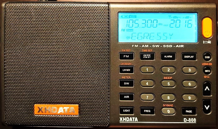
General information:
From a DSP do not expect a miracle in sound quality, but this is a quite good, cheap, and sensible pocket radio for daily listening. In conclusion this radio is very similar to C. Crane Skywave SSB (as presented before) and Digitech AR-1780 and Eton G3 Satellit, and their schematic can be used for servicing each other..
Recommendation: The radio has a quite big speaker (in diameter is approx. 7cm), almost the maximum which can be mounted into its plastic chassis but sounds like a cheap pocket receiver. The reason is the low capacitance value of the output capacitors. If we consider the speaker as an 8ohm resistor, with 100uF capacitor the cutoff frequency is approx. 200Hz. The used capacitor was a very cheap model with poor parameters (high dissipation factor and high ESR). I changed both of them (C145, C153) with a 470uF/6.3V Nichicon Fine Arts type (they are a bit bigger, but still can be mounted in the same position), and now the cutoff frequency became 42Hz. Now the music on FM via speaker is much better, and via headphones became alive! The second modification was to decrease the output noise which can be heard at minimum volume via headphone. For that I inserted one 6.8nF C0G MLCC capacitor connecting both outputs of audio amplifier (between + pins of above mentioned output capacitors), 2 pcs of 150pF connected in parallel with the output amplifier's feedback resistors (R122, R123). Is better if the capacitors are SMD (can be soldered on top of resistors), C0G or NP0 type. This method are used in old FM receivers, called "high-blend" filter, and eliminate the noise with opposite phase from the signal, and the second one is a low-pass filter. Try both modifications, and you will be surprised by this improvement in sound quality.
The original Li-ion accumulator can be replaced with a higher capacity one. Now I use a 3000mAh type, and the listening time is 50% longer. The charging time also increased accordingly, but does not cause any problem.
Remark: when you purchase as a new one, the radio can be powered on just if you put it on a charger.
Squelch capability: is not mentioned in the User manual, but can be activated by long pressing the Tuning knob, and waiting for the "Squelch" readout to show up at the bottom of the display. While still pressing in the Tuning knob you can adjust the Squelch level by turning the Tuning knob clockwise to raise the squelch level from 1 to 9. Although this Squelch function is available on all bands on the D-808, but it is apparently useful only on the AIR band.
Related links:
Georges' review of the XHDATA D-808, is a good revies on The SWing Post about his experience with this radio.
Reviews For: XHDATA D-808 Portable, is a revies on EHAM radio.
XHDATA D-808 AM/FM/SW/SSB/Airband Portable Radio, is a revies on RadioJayallen, the most detailed what I found.
A detailed review of the XHDATA D-808 and comparison with the Tecsun PL-660, is a revies made by 13dka with several replies.
PL-330 or D-808?, is Kevin's blog, in which he objectively compare the Tecsun PL-330 with XHData D-808 from several aspects, pros and cons.
Yamaha
Nippon Gakki Co. Ltd. (currently Yamaha Corporation) was established in 1887 as a reed organ manufacturer by Torakusu Yamaha in Hamamatsu, Shizuoka Prefecture and was incorporated on October 12, 1897. In 1900 the company started the production of pianos. The first piano to be made in Japan was an upright built in 1900 by Torakusu Yamaha, founder of Nippon Gakki Co., Ltd. - later renamed Yamaha Corporation. The company's origins as a musical instrument manufacturer are still reflected today in the group's logo-a trio of interlocking tuning forks.
Yamaha has grown to become a leading manufacturer of semiconductors, audio/visual, computer related products, sporting goods, home appliances, specialty metals and industrial robots.
Yamaha R-700
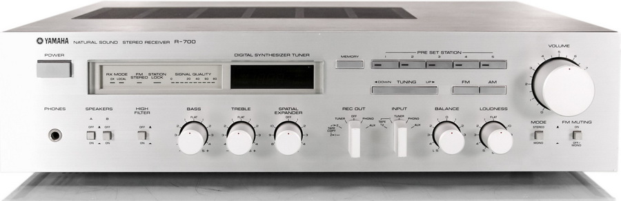
General information:
Good things:
Difficult, problematic items:
The R700 is almost identical to the R900 model. Differences: R900 output power is 70W (higher supply voltage +-55.4V, different driver and power). ICs: STK3076 and STK1070II), the RIAA preamplifier is more appropriately built and can select the cartridge: MM or MC (all other sections, like radio unit, control unit, etc. are completely same). The RIAA includes a differential input generated by two SD786 transistors per channel. Both types use the same PCB because the ICs are pin compatible, and in the case of RIAA, the differential input with the cartridge switch is removed from R700. If you want to have a more accurate RIAA preamplifier, I propose updating your R700's RIAA to the R900 version - regarding PCBs compatibility. The main power filtering capacitors are 12000 uF/63V in R900.
Often defects: the power amplifier IC is burned, and including with its driver is difficult to be replaced. In March 1984, Yamaha delivered and updated service information for the amplifier section, which included extra capacitors that prevented self-oscillation including the updated schematic and PCB drawing (without giving capacitor values, just their placements! - C407 and C408). The most essential update was to disconnect the grounded legs of resistors R405 and R406 and install a 100uF/6.3V capacitor between them, which would limit the bandwidth at lower frequency.
Yamaha T-700
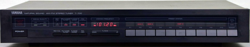
Returning to T-700, is a middle-class FM/AM tuner from T-300/500/700/1000 series. Facilities: has a Record Calibration (333 Hz 50% modulated signal), digital frequency readout, FM noise filter, 10 station memory, and CSL (Computer Servo Locked Synthesizer Tunning System).
General information:
Good things:
Difficult, problematic items:
Modifications:
Power line: all capacitors changed to dry electrolytes, except the very big values or high voltage types. Values changed: C101, C106 C128, C193 47uF/16V; C180, C182, C199 270uF/16V; C197 100uF/63V; C198 100uF/16V, C200 3300uF/25V. Because this is one side PCB, some jumpers also can be used to decrease the noise transmitted by the power line: J197 replaced with 2.2uH (supply of front end), J140 also with 2.2uH (supply of IF amplifiers), and J168 with 100uH (supply of MPX decoder). Added capacitors as decoupling elements: 1nF/50V SMD C0G at power input of front end (after J197/2.2uH coil), 10nF/50V SMD C0G between pin7 and GND of IC103 (prescaller), 680uF/16V on pin1 and GND of IC105 (MPX decoder). Received an EMI filter at the output of power transformer, made with 2 pcs of 1uF/100V pp capacitors and one noise canceling (EMI) double-2 windings coil, both having 6.6mH inductance.
Audio signal: changed to C139 100nF/100V pp, C155 and C156 to 4.7uF/50V pp.
On thing impressed me: Conclusion: with a bit better sensibility, no specialized IF ICs, has very low noise and clear sound with very low distortion - and this concept was followed during several tuner-generations by Yamaha tuner designers. Unfortunately, this was not rewarded by customers, because they buy systems, the whole system (turntable, tuner, cassette player, and amplifier), not just the tuner. With the actual filtering, including the EMI, the tuner is immune to any LED lamp or PWM voltage regulators connected to the same power line distributor as the tuner.
Yamaha R-3
General information:
Good things:
Difficult, problematic items:
|
88.1 MHz |
Info Radio - news |
31 dB/u |
||
|
88.8 MHz |
Maria Radio - religious |
40 dB/u |
||
|
89.5 MHz |
Radio1 - Pop music |
60 dB/u |
||
|
90.3 MHz |
Tilos |
49 dB/u |
||
|
90.7 MHz |
Bartok - classical music |
17 dB/u |
||
|
90.9 MHz |
Jazzy - Jazz music |
31 dB/u |
||
|
91.7 MHz |
Maria Radio - religious |
15 dB/u |
||
|
92.1 MHz |
Klasszik - classical music |
52 dB/u |
||
|
92.9 MHz |
Spirit - general |
34 dB/u |
||
|
94.2 MHz |
Trend FM - general |
45 dB/u |
||
|
94.8 MHz |
Petofi - pop and general |
46 dB/u |
||
|
95.3 MHz |
Karc FM - political |
43 dB/u |
||
|
95.5 MHz |
Kossuth - general |
21 dB/u |
||
|
95.8 MHz |
Slager - general |
51 dB/u |
||
|
96.4 MHz |
Base FM - pop music |
34 dB/u |
||
|
96.9 MHz |
Regina, Slovakian - general |
5 dB/u |
||
|
97.3 MHz |
Maria Radio - religious |
25 dB/u |
||
|
98.0 MHz |
Cafe Radio - pop music |
43 dB/u |
||
|
98.6 MHz |
Manna FM - general |
47 dB/u |
||
|
99.5 MHz |
Best FM - general |
55 dB/u |
||
|
99.8 MHz |
Danko - popular music |
8 dB/u |
||
|
99.9 MHz |
Best FM - general |
13 dB/u |
||
|
100.3 MHz |
Radio Dikh - Gypsy radio |
43 dB/u |
||
|
100.8 MHz |
Danko - folk music |
52 dB/u |
||
|
101.6 MHz |
Sola - religious |
34 dB/u |
||
|
102.1 MHz |
Katolikus Radio - religious + classical music |
48 dB/u |
||
|
102.7 MHz |
Petofi - general |
25 dB/u |
||
|
103.3 MHz |
Retro Radio - retro music ('60, '70 and '80) |
57 dB/u |
||
|
103.9 MHz |
A Rock - rock music |
49 dB/u |
||
|
104.3 MHz |
Slovakian radio |
6 dB/u |
||
|
104.7 MHz |
Retro Radio - retro music ('60, '70 and '80) |
21 dB/u |
||
|
105.3 MHz |
Bartok - classical music |
53 dB/u |
||
|
105.6 MHz |
Bartok - classical music |
16 dB/u |
||
|
105.9 MHz |
Sport radio - sport and music |
37 dB/u |
||
|
107.2 MHz |
Kossuth - general |
11 dB/u |
||
|
107.8 MHz |
Kossuth - general |
49 dB/u |
||
Stations list was updated at 05.11.2024. In total 36 individual frequencies and 26 different radio programs.
Useful links
The FM ceramic filter page - by Bruce Carter. Is a short presentation of ceramic filters theory and practical recommendations
The 10.7 MHz IF filters, is a ceramic IF filters page from the old Tuner review page. Can be downloaded Murata IF filter catalog from 1991!
Matching matters: Case study of 110 kHz narrow filters - by fmdxing. The editor of this website has modified his Denon TU-1500RD radio with 110 KHz filters in the 'narrow' tuning mode in 2006 and saw a marked improvement in reception.
How to select a FM tuner for 88-108MHz DX by Todd Emslie - a good article and tuners comparison
Receivers for FM DX recommended by New Zeeland Radio DX League
Hungarian DXers page - contains all Hungarian and its surrounding countries FM stations frequencies, propagation info etc. Just in Hungarian
FM Tuner Information Center is a good collection of vintage stereo tuners.
FM Tuner Information Center has also a DIY or mod section. I highly recommend to read general DIY and modification tips, sometime you can find ideas/recommendation directly for your tuner
List/database of best vintage tuners, made by audiophile panelist Jim and published on FM Tuner Information Center. Can be a good reference if you would like to buy a vintage tuner. The list was made between 2002-2006, and in 2016 received some updates as Shootouts 2.0
FM Pre-Emphasis and De-Emphasis is a good explanation of de-emphasis (time constants) used by FM transmitters in Amerika (75us) and Europe (50us).
HD Radio Self-Noise - a good page about HD transmission used in America, and a list of tuner which are immune to this noise generated by HD transmission.
Superheterodyne Receiver - a collection of theory of superheterodyne receivers from Science Direct.
Double & Triple Conversion Superheterodyne Radios - a good explanation of double conversion reason and effect used in AM radios from Electronics Notes.
Marantz FAQ: "Frequently Asked Questions" - a good FAQ collection well explained, including also technical functions of tuners, signals, etc.
FM Frequencies for Budapest a webpage, which can list all receivable FM stations frequesncies in a defined location.
Tips to repair tuners:
First rule: don't touch anything until you have confirmed which part is the discriminator coil as random twiddling will ruin any tuner. Note the position of anything you touch so that it can be returned to its original setting if the desired results are not obtained. Once identified, buy or make a non-metallic tool with which to adjust the coil's core.
For tuners with digital displays, tune to a strong local station whose frequency is known to you then set the tuning so the display is correct (even if the sound is then distorted or absent). If possible, with the model in hand, next select mono reception and adjust the discriminator coil gently and carefully for the best reception. Half a turn in one direction or the other is normally all that is required. Try some other stations and confirm that they appear at the correct frequency.
When it comes to mechanically tuned models the process is different. Tune to a local station again and turn on the set's AFC (automatic frequency control) function. Adjust the discriminator for the best sound quality as above, or if the tuner has a balance meter adjust to center the needle. That is normally all that is required.
If the stereo decoder still doesn't work and it's a PLL (Phase Locked Loop) type, the 19kHz oscillator may be out of adjustment. This is normally a preset resistor near the chip (PLL types are invariably IC based) and slight adjustment may be required. Never touch the 'separation' adjustment as an FM stereo signal generator is required to set that up that correctly.
Note: If you need the owner or service manuals for above presented radios (I have almost all of them), or you see some problems on webpage, broken links, please contact me.