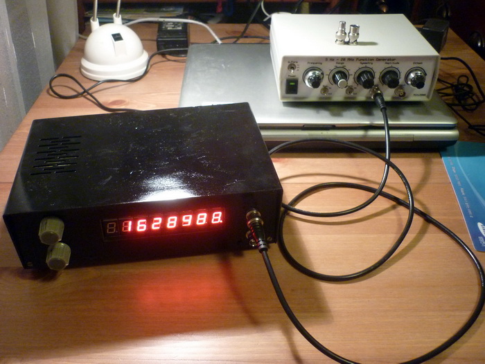
Frequency counter

Below project is under construction!
The heart of this circuit is the ICM7226A, which is a fully integrated universal counter and LED display driver. Contains a high frequency oscillator, a decade timebase counter, an 8 decade counter and latches, a 7 segment decoder, digit multiplexer and drivers. Accepts a maximum frequency of 10MHz in frequency and unit counter modes, and 2.5MHz in other modes.
ICM7226A can function as:
- frequency counter
(till 10MHz) from input A
- period counter from
input A,
- frequency ratio (fA/fB) - both inputs,
- time interval counter between A to B,
- totalizing counter from input A,
- self oscillator
frequency display.
In frequency mode is possible to select the accumulation times/ranges, which can be: 0.01s, 0.1s, 1 s, 10s or external.
The schematic can be
seen below:
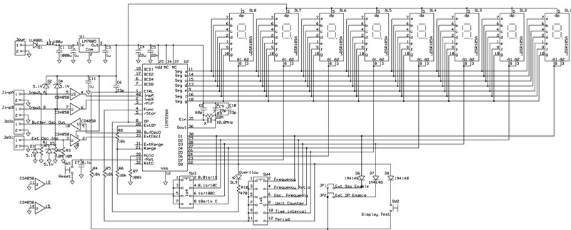
The
mainboard contains all possible functions - considering eventually
extension of project.
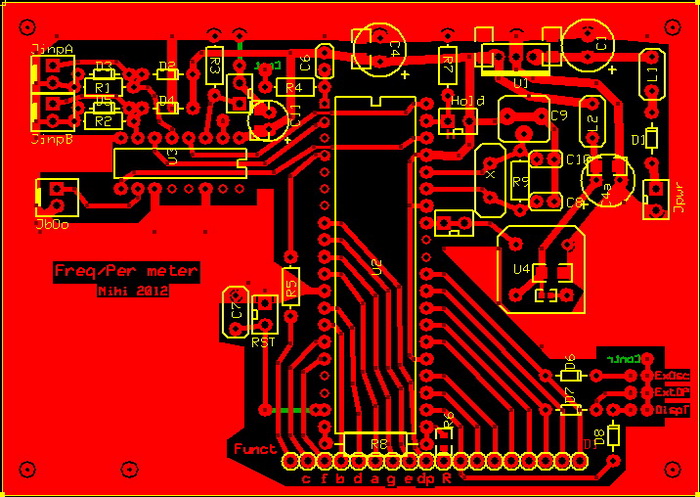
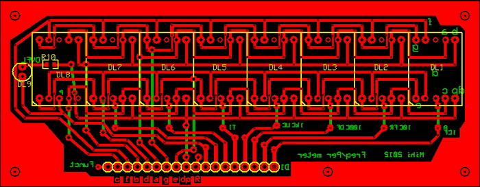
The
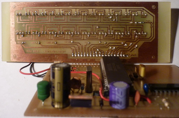
display board PCB:
Because the ICM7226A accepts just CMOS levels at inputs (transition should be minim. 50% of power supply), was necessary to:
- make input circuit, which can inscrease its sensibility,
- make a prescaller, to increase the measurement range till 1.1GHz, instead of original 10MHz.
To
solve above mentioned items, I planned 2 additional circuits - mostly
to help frequency measuremenets. All prescallers above 1GHz has a
deficiency: their minimal input frequency shouls be above 30MHz. That
means, are necessary 2 input circuits: one for below 10MHz and one for
above.
The input stage
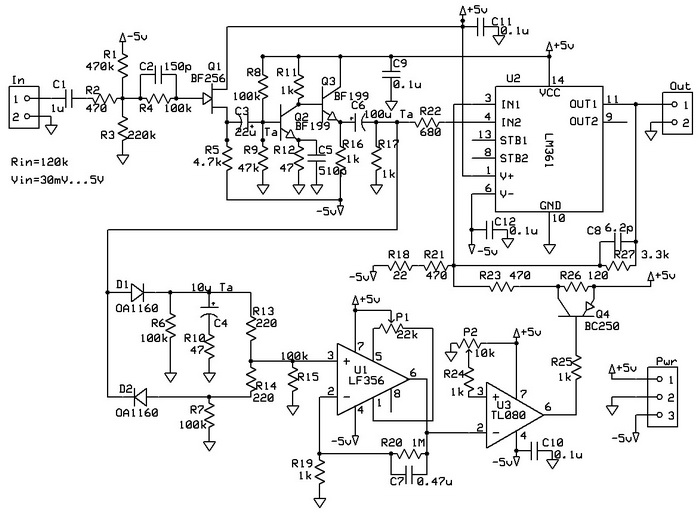
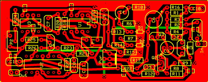
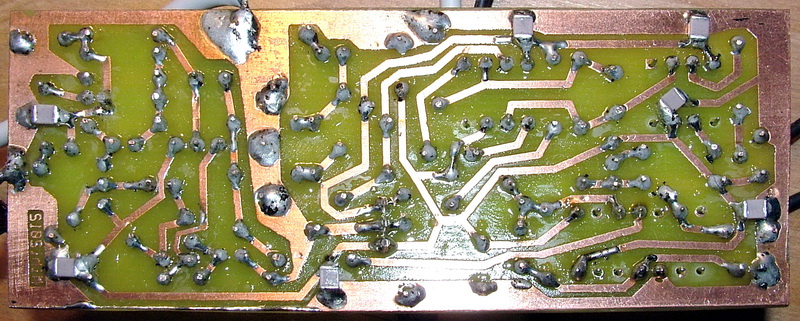
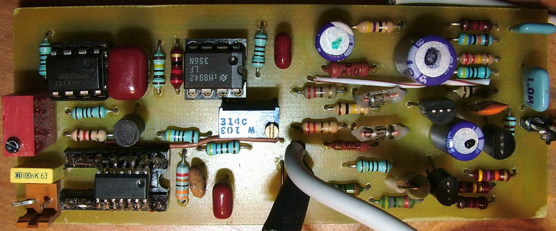
for 20Hz-10MHz (can work till 30MHz with adequate counter), with Ri=120kohm, Vin=30mV-5V:
The
circuits contains a preamplifier (Q1 as impedance mathing, Q2 as
amplifier 10-15x, and Q3 as low impedance driver), an ultra fast
comparator (U2 as LM361 or NE529). U1 and U3 are forming an automatic reference
voltage to establish a high precision on wide frequency and input
voltage range. Adjustment can be made with P1, P2, R18, R26 and R27
(R18, R26 and R27 are the closest values to ideal situation, but can be
a
bit different case by case, depending by used components tolerance).
With P1 should be adjusted a 0.5...1V offset
voltage at U1 output, and with P2 must be found the 5V transition point
for U3 output. Analog part can be powered from +-15V, but from +-5V
also works well, digital part's +5V is same with analog part's +5V.
The input stage for 10MHz-1.1GHz, with Ri=51ohm, Vin=30mV-5.5V:

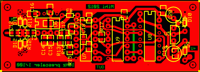
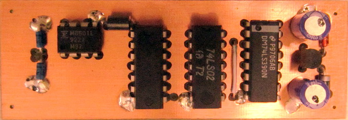
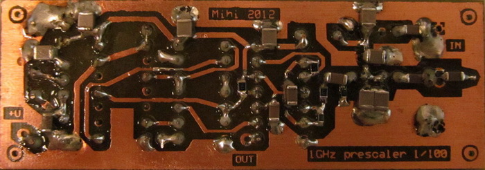
MB501L is a two modulus prescaller, which can divide input frequency till 1.1GHz with 64/65 or 128/129 - and has an ECL level output (Voutpp=1.6V).
At input the circuit are protected by 2 diodes D11 and D12 (can be Ge or Schottky, ex. 1N5711 ). The ECL-TTL level conversion are formed by 3 NAND gates of U7. The first is an AC coupled linear amplifier with 10x amplification. The second makes further amplification and the third forms the prompt TTL signal. This level conversion are adjustment free, temperature independent and easy to be reproduced. After that the signal goes through two divide-by-5 circuits of U8, which with U9's gates forms two dividers by 4/5, resulting the total division of prescaller:
1/64 x 4/5 x 4/5 = 16/1600 = 1/100.
Should be remarked, that dual rate divider, such as the one presented here, supplies an output signal whose levels ratio is irregular. Fortunately this is not a problem for (most) frequency meters (the output signal is not suitable for PLL based circuits!).
The power supply was increased to 5.7V, to push the highest input frequency of the U6 (MB501L) to the maximum mentioned in its specification.
Note:
the prescaller may be coupled with tested circuit via a short cable, or
inductively by a wire loop. Both methods require the prescaller to be
located fairly near the circuit, but avoid the risk of signal
attenuation by the capacitance of long (coaxial) cables.
The
box without prescaller and input circuit:
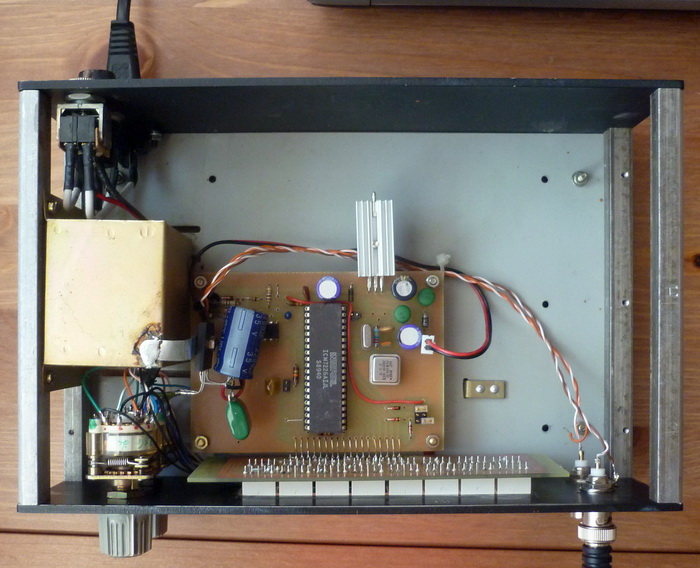
Already
finished (unit counter mode test):
