The SDS Lab's headphone amplifier
The presented
amplifier was published on the net by Sheldon D. Stokes as SDS
Lab's Headphone Amplifier.
I don't would like to repeat the
amplifier's circuit description, you can find it in detail in the pdf
file. The output mosfets in final construction are IRF610 and IRF9610
(paired, and have a low gate capacitance - 140pF), and the opamp is
OPA2132 (I also try the NE5532
and SSM2275, but I did not like their sound character - probably they
was
not compatible with mosfet's sound?). The bias
circuit was also modified (recommended by Jeffrey Baker), because the
original with 4 LEDs are noisy and their thermal stability is very
poor. The setting was made for my 32Ω Sennheiser HP497, for this reson
the
idling/bias current is 100 mA (you can measure 1 V on 10Ω/2W source
resistors). The gate resistors value is 100Ω (they helps to keep the
amplifier from oscillating), and should be installed as close to the
MOSFET gate leads as possible. In comparison with original schematic
you can find more capacitors, all with low ESR. In bias circuit both
capacitors must be selected carefully: C10 must be MKP (polypropilen)
and C11 to be audio grade.

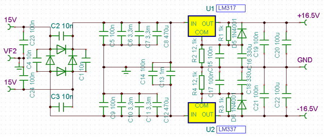
With power supply I meet one, till now neglected problem. After I finished the whole amplifier, I measured 20mV DC at output! After measuring the power supply more carefully, I recognise a difference of 90mV in absolute value between symmetrical outputs. The reason: the internal reference voltage of LM317 and LM337 can be between 1.20-1.30V (conform specifications) - and I calculated with recommended nominal value: 1.25V. To echilibrate, I solder an 1MΩ in paralel with 12kΩ in negative supply part (but that depends case by case, can be measured and calculated). Now the DC output of amplifiers are < 2mV! For better performances must be changed both regulators to noiseless types.
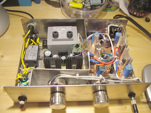
Close to each mosfets you can find its buffer capacitor (4700µF with low ESR). In my opinion the buffer can be as close as possible to mosfet drivers. This picture was made, when I use SSM2275 opamp. The board is 2 side Cu type, and one side is the ground plane. Around mosfets are scratched to be galvanically separated.

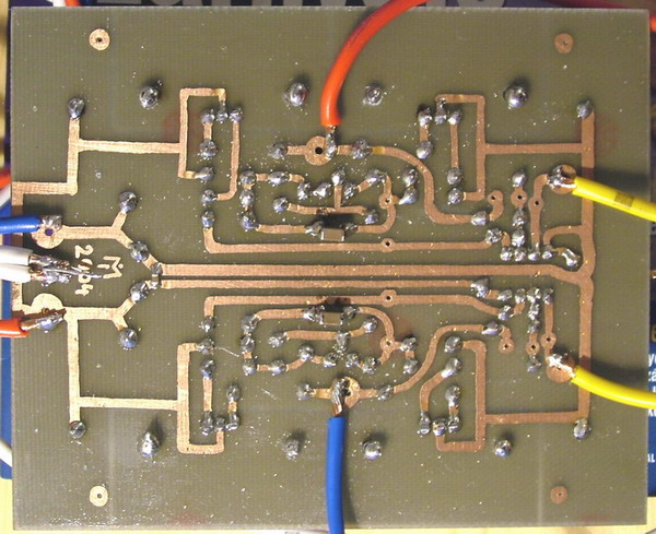
This is my PCB - sometime, when is a simple board I made it myself, because is faster. You can recognise the SMD MLCC capacitors - it was 22µF X7R, but was replaced with 1µF MKP polypropylene capacitor - to eliminate the inductive effect of electrolytic capacitor.
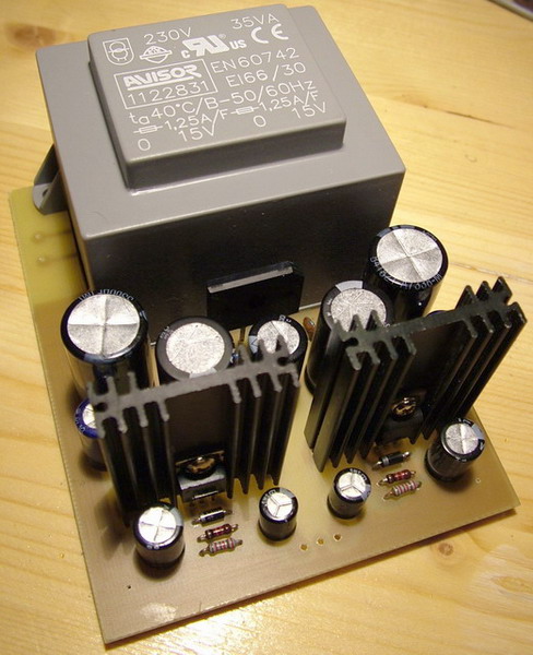
Here is the final assembly. Please recognise the power supply is separated from amplifier part. Regarding high capacitors, during switch on, appearing transient oscillations on the outputs (delayed and/or not in same time charging of capacitors) which can deteriorate your headphone. That effect is eliminated with a delay circuit setted for 7 seconds on output of amplifier (circuit in power supply side, the relay mounted on amplifier side).
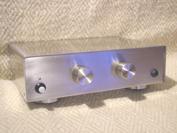
The front of headphone amplifiers (the volume control are made with two potmeters - Cosmo type, wire-bound 10k, logaritmic, 2W. Reason: I didn't find very good stereo potmeters when was made this amplifier.
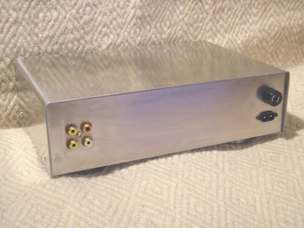
The back side of headphone amplifiers.
Mostly I like to use it with my 600Ω AKG 141 Monitor headphone - the sound is very clean, balanced, no any additional colors, and is complettely without any noise!
Measured parameters:
Output DC offset: < 2mV
Noise (Max volume, no input) (Vrms): 0.01mV
S/N (Max volume, 1kHz): 85dB
Channel separation (Max Volume on 32ohms): 86dB
Gain Voltage: x2.2
Zin: 100KΩ
Max Vinput (for load 32Ω): 2.5Vrms or 5.8dBm in 600Ω
Output power (load 32Ω, max volume, Vin max 2.5V): 1W
THD at 20kHz: lower than 0.01%
Heatsink temperature at full power (1W) after 5 hour operation (covered): 43 º C
Power supply ripple noise (Full load): < 0.1mV RMS