The Heed Canamp clone headphone amplifier
This headamp was designed Heed Audio Ltd team. First of all, before you would like to start to build this headphone amplifier, I would like to mention a few things, to not be confuse:
- this headphone amplifier is not an exact copy of the original one. I had possibility just to listen it, never got possibility to open it.
- I try to
sellect all available photos from net about this headamp, and analyzing
them, I try to
make a similar one - that is the reason why my PCB design looks very
similar.
-
on the net you can find similar schematics, but considering the
component arrangements and my personal requirements, those values gives
me the best performance.
- Updating opportunities: to redesign for minimal offset, keeping this natural and warm sound.
An other important thing is the component's selection. I know Heed Audio team spends hundreds of hours to match each componant till finally get the best sounding headphone amplifier. That is confirmed by a loud international rénumé which can be found on many audiophile forums regarding this amplifier.
Considering
above mentioned reasons, any clone will not sound like the original
one, because as diyer, you will never have time to make such deep
development to find the best component kit for this design.
Putting together the world best components will not guaranty to you the best sounding headphone amplifier!
The homepage of this Camamp can be found here.Unfortunately on webpage you can not find any detailed specification. Here are my clone's data:
Output DC offset: < 12mV
S/N (Max volume, 1kHz): >90dB
Channel separation (Max Volume on 32ohms): >90dB
Gain Voltage: x2.8
Zin (with volume control potentiometer): 10kΩ
Output power: >900mW on 32 ohm, >80mW on 600 ohm
Power resistor temperature after 8 hour operation: 62 º C
Power transistor temperature after 8 hour operation: 55 º C
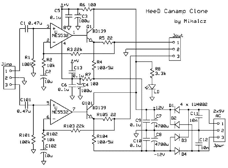
The
schematic:
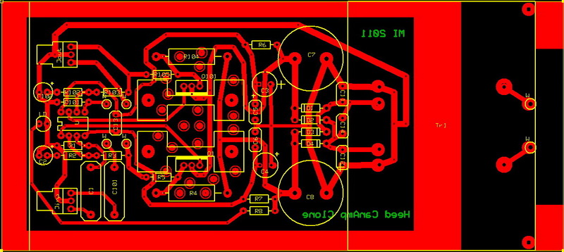
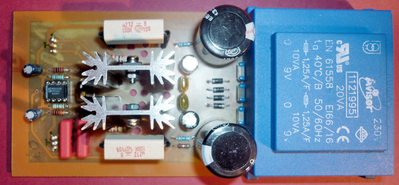
The printed circuit board:
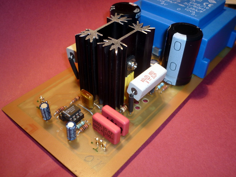
The assembly before to be mounted into chassis
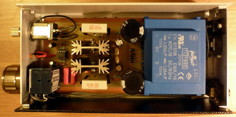
Top view of assembly
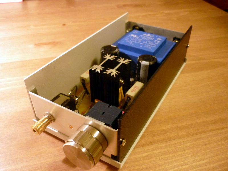
Assembled into chassis, the front side - uncovered. Can be seen the headphone output, the power led and the volume potentiometer.
The chassis from backward, with inputs and power switch.
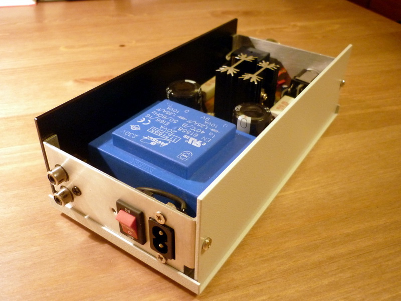
Top view.