Resistors selection
Choosing the resistor types comes up quite often in DIY hifi and high-end systems. If you are looking around on dedicated webpages, audiophile magazines, you will be very confused - some people will recommend only using carbon composition resistors, others will tell you that metal film resistors are better, etc.
From the noise point of view, there are 3 main things to take into consideration:
- Thermal noise: is mainly dependent on temperature, bandwidth, and resistance
- Shot noise: is dependent on bandwidth and average DC current
- Contact noise: is dependent upon average DC current, bandwidth, material geometry, and type
Thermal noise
The thermal noise of a resistor is:
![]()
where:
En =is the rms noise
voltage
k = Boltzmann's
constant
T =
temperature(Kelvin)
df = noise bandwidth
R = resistance
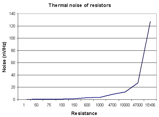
The characteristics of thermal noise have a Gaussian probability density function, and the noise of the two separate sources is uncorrelated white noise, the total noise power is equal to the sum of the individual noise powers. If you model the individual resistors as noise generators, the output noise voltage will be equal to the square root of the sum of the squares of the individual noise sources. The above equation shows that the noise varies in direct proportion to the square root of the resistance and temperature.
In general, the thermal noise of any connection of passive elements is equal to the thermal noise that would result from the real part of the equivalent total impedance. If we are dealing with pure resistances, the thermal noise is equal to the thermal noise produced by an equivalent resistance. Therefore, the thermal noise of a 1K carbon resistor is the same as a 1K metal film; it is independent of the resistor's material.
For ex. if you take two resistors of half the value and square the square root and add them and take the square root of the sum, you end up with the same value as you would if you took the square root of a single resistor of twice the value. Therefore, the total noise remains the same - but the heat dissipation surface was increased (regarding currents heating effect), and the temperature of resistors will be lover. That is the reason, why is much better to use big resistors or more parallel-connected. The most efficient way to reduce the noise is to reduce the resistance value. This is why you don't want to use 10M resistors on your input stage.
Contact noise
Contact noise is dependent on both average DC current and resistor material/size. The most significant contributor to noise in high-end amplifiers is the use of low-wattage carbon composition resistors. Since the noise is proportional to resistor size, the use of 2W carbon composition resistors will improve the performance over that of 1/2W resistors. Studies have shown a factor of 3 difference between a 1/2W and a 2W carbon composition resistor operating at the same conditions.
The predominant noise in carbon composition, carbon film, metal oxide, and the metal film is composed of contact noise, which can be very large at low frequencies because it has a 1/f frequency characteristic. Wire-wound resistors do not have this noise, only resistors made of carbon particles or films. This noise is directly proportional to both the current flowing in the resistance and a constant that depends upon the material the resistor is made of.
If no current (AC or DC) flows in the resistor, the noise is equal to the thermal noise. The contact noise increases as the current are increased. This means that for low noise operation, the DC and AC currents should be kept low.
The material and geometry of the resistor can greatly affect the contact noise. Therefore, if you double the power rating of the resistor, which increases the size and area, you will reduce the contact noise generated by the resistor.
Shot noise
Shot noise is dependent upon current, so the more average DC current through a resistor, the more noise you get. To reduce this type of noise, you must keep the DC current to a minimum. This is best done in the first amplifier stage or in low-level stages such as RIAA correctors or microphone preamplifiers, where it is the most critical. Unfortunately, higher DC currents usually sound better in tubes and class A power amplifiers, so it is a trade-off. The best practice is to use an inductorless wire-wound or metal film in these applications unless you are making a high-frequency amplifier where the inductance of the wire-wound resistor comes into play.
Conclusions
A few practical notes:In general, for low-noise design:
- Keep resistance values low, because thermal noise is directly proportional to the resistance value.
- Inductorless wire-wound resistors are the best choice for noise, followed by metal film, metal oxide, carbon film, and lastly, carbon composition. However, wire-wound resistors are not readily available in large resistance values and are usually inductive. Bear in mind, however, that many people prefer the "sound" of carbon comps, claiming they sound warmer than film or wire-wound types. This is possibly due to distortions generated by the modulation of the contact noise current by the AC signal. Since this noise has a 1/f frequency characteristic (similar to pink noise), it is more pleasing to the ear than white noise. However, pleasing noise is still noise, and in my opinion, it should be reduced to the lowest possible level. The signal distortion is a different topic altogether.
- Use the largest practical wattage resistors (unless you are using wire-wound resistors) because contact noise is decreased in a larger geometry material and the temperature of the resistor(s) will be lower.
- Keep the DC and AC currents to a minimum (especially in the first stage) because contact noise is proportional to current.
- Don't forget that potentiometers are also resistive elements, and are almost always carbon composition, and generally are large values (such as 22k-100k in commercial solid-state amplifiers, and around 1M for the volume control in tube amplifiers). These can be a major source of noise! For absolute lowest noise, wire-wound or conductive plastic element pots should be used, again, the lowest practical value, and the largest practical power rating.
- The first stage of an amplifier is the most critical; to maximize the overall amplifier signal-to-noise ratio, the first stage gain should be maximized. This will raise the signal level farther above the noise floor of the following stages
- Since noise is proportional to resistor value, the 1M to the ground
resistor on the first stage of the amplifier will create much more noise
than the 68K grid resistor, because the value is 14.7 times
larger. This means that carbon comp vs. metal film is more
noticeable and important for the 1M resistor than the 68K input
resistor. However, when a phono cartridge or microphone is
plugged into the amplifier, the pickup resistance/inductance and
cable capacitance is in parallel with the 1M grid resistor, so its
effect on noise is greatly reduced. When they are unplugged or
turned down, the 68K series grid resistor becomes the
predominant noise source. Depending on the tube type and/or
input stage topology, the resistor noise may be greater than the
tube's/semiconductor's referred input noise. To reduce the noise to
a minimum, use the smallest possible input grid resistor value that
still provides RF suppression.
- Since resistor noise is proportional to current flow, a 100K grid resistor is going to be quieter than a 100K used as a plate resistor. There is around 1 to 2 mA of current flow in a typical plate circuit, but the grid current flow is practically negligible. This means that it is better to use metal film for plate resistors. The exception to this rule comes when two resistors are used as a voltage divider from the plate of one tube to the grid of the other. There is no grid current flowing, but there is a current flowing in the voltage divider string, so metal films should be used in these positions for the lowest noise.
- Lastly, the noise contribution is greatest at low-level stages, such as input stages and effects loop recovery stages, so the plate resistors, grid-to-ground resistors, and grid divider attenuation resistors in these locations should be metal films for lowest noise, where there is little gain from that point to the output, can use noisier resistors without adding too much to the overall noise level of the amplifier because the signal level at that point is many times greater than the noise level produced by the resistors.
- One more consideration for resistors used in tube amplifiers: it is sometimes overlooked that resistors have a max voltage rating. The 1/2 Watters and some 1 Watters usually are only rated for 250-350V. Be sure to get a resistor rated for the appropriate voltage in the amplifier. For ex. only 1W, 500V min (continuous, 1000V surge) or 2W, 750V rated resistors.
There are three types of resistor color coding. They have a different
number of color bands and hence provide different information. This is
illustrated by the next table. You can calculate the value of an
unknown resistor by entering its color code in the fields below the
table. Please remember, when you meet resistors just with 3 colors,
that means the 4th "color" is none, their tolerance is 20% (they are
not for HiFi!).
|
|
|
|
| 6-band
color
code
3 digits, multiplier, tolerance, |
5-band
color
code
3 digits, multiplier, tolerance |
4-band
color
code
2 digits, multiplier, tolerance |
| Enter all the color bands. | Select None for field 6. | Select None for fields 3 and 6. |
And finally here is the complete color codes table. The band number
that contains the given value is shown in braces [ ] and the table is
easy to use by itself. The 6th color code - thermal coefficient - are
infrequent, you can meet just on high precision resistors for
instruments.
| Color | 1st band | 2nd band | 3rd band | Multiplier | Tolerance | Temp. Coefficient |
|---|---|---|---|---|---|---|
| Black | 0 | 0 | 0 | ×100 | ||
| Brown | 1 | 1 | 1 | ×101 | ±1% (F) | 100 ppm |
| Red | 2 | 2 | 2 | ×102 | ±2% (G) | 50 ppm |
| Orange | 3 | 3 | 3 | ×103 | 15 ppm | |
| Yellow | 4 | 4 | 4 | ×104 | 25 ppm | |
| Green | 5 | 5 | 5 | ×105 | ±0.5% (D) | |
| Blue | 6 | 6 | 6 | ×106 | ±0.25% (C) | |
| Violet | 7 | 7 | 7 | ×107 | ±0.1% (B) | |
| Gray | 8 | 8 | 8 | ×108 | ±0.05% (A) | |
| White | 9 | 9 | 9 | ×109 | ||
| Gold | ×0.1 (10?1) | ±5% (J) | ||||
| Silver | ×0.01 (10?2) | ±10% (K) | ||||
| None | ±20% (M) |
Dimension and power ratings of SMD resistors
| FORM | POWER (W) |
LENGHT (mm) |
WIDTH (mm) |
| 402 | 0,063 | 1,00 | 0,50 |
| 503 | 0,063 | 1,27 | 0,75 |
| 505 | 1,27 | 1,25 | |
| 603 | 0,062 | 1,60 | 0,80 |
| 705 | 1,91 | 1,27 | |
| 805 | 0,10 | 2,00 | 1,25 |
| 1005 | 0,125 | 2,55 | 1,25 |
| 1010 | 2,55 | 2,55 | |
| 1206 | 0,25 | 3,20 | 1,60 |
| 1210 | 0,25 | 3,20 | 2,60 |
| 1505 | 3,80 | 1,25 | |
| 2010 | 0,50 | 5,08 | 2,55 |
| 2208 | 5,72 | 1,90 | |
| 2512 | 1,00 | 6,50 | 3,25 |
| MELF | 5,50 | 2,20 | |
| MINIMELF | 3,60 | 1,40 | |
| MICROMELF | 2,00 | 1,27 |
How to calculate the nominalized values of resistors?
During design process you can select the appropriate values to your calculated one. At first, you can choose the tolerance (or the class). With the next formula you can calculate the series? nominal values:
Where T the selected tolerance class total values (ex. 48, 96, 192 etc.), and n is the order in that class, its value are between 0 to T.
You have additional two rules:
- from series 48 (48, 96, 192,...) you can consider 2 decimals
- the number can be down rounded (ex for n=67 you have 2.206 - the right nominal value will be 2.21, but for n=59 you have 2.004 - the right nominal value will be 2.00!).
Standard EIA Decade Values Table (100 to 1,000 Decade)
|
|
|
Multiplying them with exponentiation of 10, you can find any values of 1% tolerance series.
Contruction, Material, and Noise Levels
Construction and materials used basically determine sound quality and noise levels. Let's check out some types.
Bulk Metal Foil
Noise typically .025uv (microvolts). Made of metal alloys with a noninductive pattern etched in metal. Their resistivity is a result of intergranular boundaries between conductive metallic crystals. The boundaries are very long and mask local site distortions. The lowest noise levels.
Metal Films
Metal films are manufacturd by sputtering a metalic layer onto a substrate. The thicker the layer, the lower the resistance. Surface imperfections and non-uniform deposits are one cause of noise. Another is generally a minute ragged or curled edge caused by grinding or laser cutting. This minute ragged or curled edge creates a path for eddy currents causing noise. These are next for being quiet.
Be careful though, as almost all so called premium metal film resistors use steel leads and sound inferior.
Metal Oxide
Depending on brand, different oxides in the conduction path as particles contact each other. However, being so irregular like a super ragged edge creates much noise. These generally use steel leads.
Carbon Film
Carbon particles is the conduction path as particles contact each other in a binder. Mechanical movement is possible with resulting instantaneous changes in resistance. Current changes paths as minute mechanical changes occur. Crackling noises occur and resistances can change at any time. Moisture is also a problem. Noise from these resistors is the highest, and as seen in the above tests, the worst sonics compared to the highest quality and expensive resistors. Some claim to make excellent sounding carbon resistors, but I would be very suspicious of such claims.
Brands that appear to come out on top
are Allen Bradley, Audio Note (not the audio equipment
manufacturer!), Vishay, Holco, Riken Ohm, Sinkoh. Caddock which is
also a very good sonic performer (although the noise is much higher
than Vishay).
Usefull links:
-
Resistors sound test, generic cement, a Duelund carbon/silver, and an auto-transformer attenuator