Capacitors selection
Choosing the right capacitor for the signal path is the most difficult process in audio system design because capacitors have complex impedance and highly depends on frequency. Distortions are produced by a wide variety of basic capacitor types, and in some cases, forms of this distortion are rather easily measurable. The basic structure consists of a dielectric material sandwiched between two electrodes or plates - the reality is far from that - showing unwanted inductance, resistance, and dielectric absorption. Different materials and manufacturing techniques produce varying amounts of these unwanted parasitics that affect the component's performance. All components, even those constructed of the finest materials and procedures, exhibit some of these artifacts and therefore should be modeled as complex impedances.
The real capcitor are presented as below:
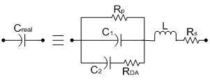
Where:
- C1 - is the ideal capacitance,
- Rp - insulation resistance or parallel resistance (dielectric's leakage - temperature and voltage-dependent),
- Rs - equivalent series resistance - ESR, limiting the minimum impedance (primarily plate-, lead-, and termination-resistance),
- C2+Rda - dielectric absorbtion,
- L - net inductance of winding and leads.
Equivalent series resistance (Rs or ESR) is responsible for the energy dissipated as heat and is directly proportional to the DF (dissipation factor). A capacitor should be depicted as an ESR in series with an ideal capacitance C1. ESR is primarily determined by plate resistance, lead resistance, and termination resistance.
Some basic formulas:
Capacitor value using material and geometrical parameters:
![]()
where A – area of overlapped electrodes, d – distance between electrodes, or the thickness of dielectric material, ε0 – is the permitivity of free space, εr - is the relative permitivity of dielectric material.
Capacitive reactance:
![]()
Inductive reactance:
![]()
Impedance:
![]()
On capacitors vectorial diagram can be seen two significant angles: θ and δ. Both are representing the losses interpreted as power factor (PF) and dissipation factor (DF):

![]()
For low values of Rs, Z ≈ Xc-XL, θ are close to 90 degree, cos θ are approx. equal with cot θ. In such case DF and PF are nearly equals for low Rs values.
The quality factor of capacitor:
![]()
Can be noted at relatively low frequencies Z are dominated by Xc. At higher frequencies Q = RS, in that point Xc = XL and the capacitor acts like a series resonant circuit. Increasing the frequency above that value, the Z is dominated by XL – showing an inductor instead of capacitor!
Dielectric constants of typical materials
|
Dielectric material |
Relative permitivity |
|
Air Teflon Polypropylene Polystyrene Parylene Polycarbonate Plyester Glass Mica Ceramics Al oxide Ta oxide |
1.0001 2 2.1 2.5 2.65 2.9 3.2 4.0-8.5 6.5-8.7 6.0-7000 7 11 |
The dielectric material is sometimes designated by another code: (note: the materials in the table below are not ceramic capacitors as implied, but plastic and paper)
| Marking | Material |
|---|---|
| KT | Polyester Film / Foil |
| MKT | Metallized Polyester (PETP) |
| KC | Polycarbonate Film / Foil |
| MKC | Metallized Polycarbonate |
| KS | Polystyrene Film / Foil |
| KPS | foil/pps? |
| MPS | Metallized pps |
| KP | Polypropylene Film / Foil |
| MKP | Metallized Polypropylene |
| MP | Metallized paper |
Please note that the table above is valid most of the time, but not always, because it is not a real standard. To be real sure, you may check the datasheet from the manufacturer in mind.
SMD capacitors will often be marked with a two-digit EIA code.
For example, A5 = 1.0 x 105 = 100,000 pF = 0.1 uF, and f9 = 5.0 x 10-1 = 0.5 pF. Simple enough.
You may also see a one-digit-plus-color-code.
Tantalums can also be found with a voltage code (instead of the tolerance code normally seen on ceramics), as shown in the table below:
 |
Example: EA7 means 100uF/25V capacitor.
The voltage ratings in case of foil capacitors are marked with number-letter system:
| Code | Max. voltage |
|---|---|
| 1H | 50V |
| 2A | 100V |
| 2T | 150V |
| 2D | 200V |
| 2E | 250V |
| 2G | 400V |
| 2J | 630V |
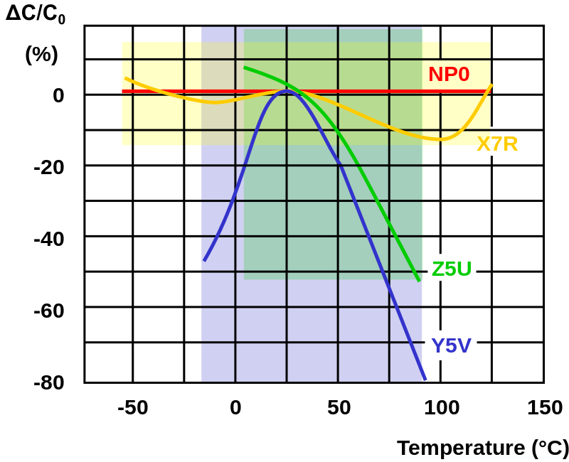
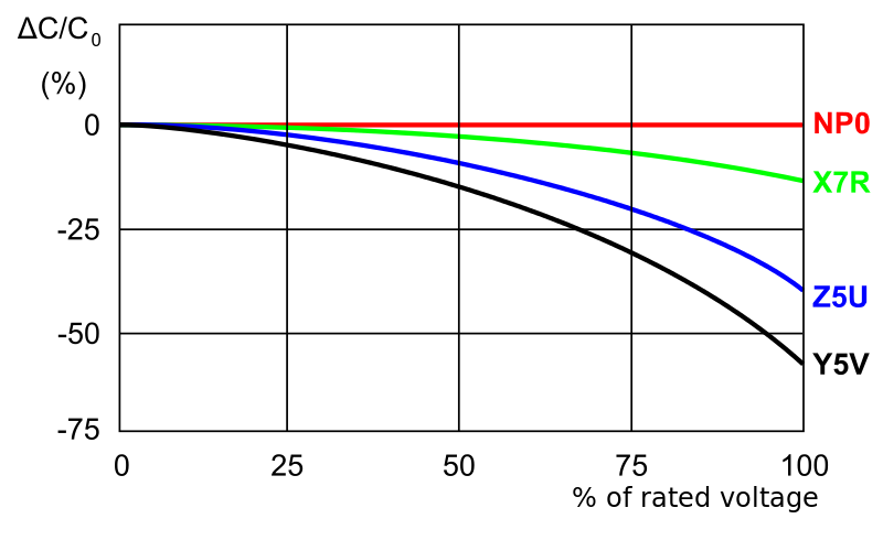
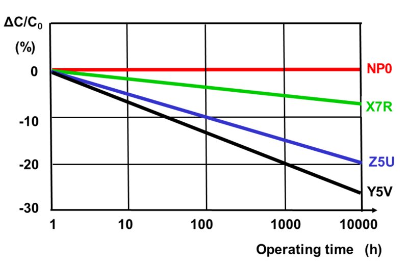
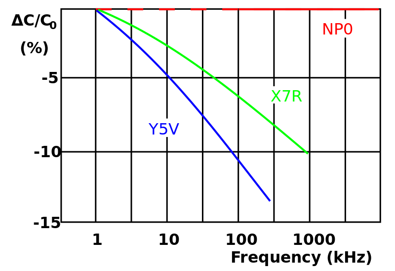
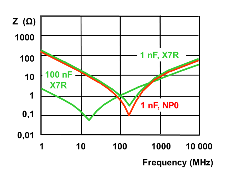
In the case of MLCC (multilayer ceramic capacitors), the used dielectric materials define the purpose of the capacitor. They are divided into 3 classes:
- Class I: offer high stability and low losses for resonant circuit applications. Most used are the C0G or NP0 (C means no temperature variation, 0 no multiplier for temperature coefficient, and G means the tolerance of temperature coefficient - in this case, 0-30ppm). In RF circuits this type of capacitors are selected in that way, that with used semiconductors or other resonant circuits the resulting temperature dependency to be zero on the used temperature range.
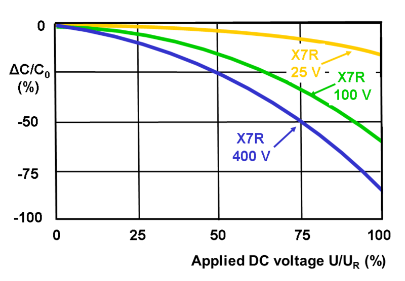
- Class II: offer high volumetric efficiency for smoothing, by-pass, coupling and decoupling applications. Have high to very high permittivity (200 to 14,000), lower accuracy and stability. The ceramic dielectric is characterized by a nonlinear change of capacitance over the temperature range. The capacitance value also depends on the applied voltage, temperature and time. Most often used types: X7R ( −55/ +125 °C, ΔC/C0 = ±15%); X5R ( −55/ +85 °C, ΔC/C0 = ±15%); Z5U ( +10/ +85 °C, ΔC/C0 = +22/ −56%); Y5V ( −30/ +85 °C, ΔC/C0 = +22/ −82%).
- Class III: are barrier layer capacitors which are not standardized anymore. Have very high permittivity, up to 50 000, and therefore a better volumetric efficiency than class 2 capacitors. However, these capacitors have worse electrical characteristics, including lower accuracy and stability.
Please check below figures for better understanding of characteristics variation:
Below table presents the application areas by dielectric type of capacitors:
| Capacitor type | Dielectric used | Features/applications | Disadvantages |
| Paper | Paper or oil-impregnated paper | The impregnated paper was extensively used for older capacitors, using wax, oil, or epoxy as an impregnant. Oil-Kraft paper capacitors are still used in certain high voltage applications. Has mostly been replaced by plastic film capacitors. | Large size. Also, the paper is highly hygroscopic, absorbing moisture from the atmosphere despite plastic enclosures and impregnates. Absorbed moisture degrades performance by increasing dielectric losses (power factor) and decreasing insulation resistance. |
| Metalized paper | Paper | Comparatively smaller in size than paper-foil capacitors | Suitable only for lower current applications. Has been largely superseded by metalized film capacitors |
| PET film (KT, "greencap", Mylar) | Polyester film | Smaller in size when compared to paper or polypropylene capacitors of comparable specifications. May use plates of foil, metalized film, or a combination. PET film capacitors have almost completely replaced paper capacitors for most DC electronic applications. Operating voltages up to 60 kV DC and operating temperatures up to 125 °C. Low moisture absorption. | Temperature stability is poorer than paper capacitors. Usable at low (AC power) frequencies, but inappropriate for RF applications due to excessive dielectric heating. |
| Polystyrene (KS) | Polystyrene | Excellent general-purpose plastic film capacitor. Has excellent stability, low moisture pick-up, and a slightly negative temperature coefficient that can be used to match the positive temperature co-efficient of other components. Ideal for low power RF and precision analog applications | Maximum operating temperature is limited to about 85 °C. Comparatively bigger in size. |
| Polycarbonate plastic film (KC) | Polycarbonate | Superior insulation resistance, dissipation factor, and dielectric absorption versus polystyrene capacitors. Moisture pick-up is less, with about ±80 ppm temperature coefficient. Can use full operating voltage across entire temperature range (−55 °C to 125 °C) | Maximum operating temperature limited to about 125 °C. |
| Polypropylene plastic film (KP = foil, MKP = metalized[a]) | Polypropylene | Extremely low dissipation factor, higher dielectric strength than polycarbonate and polyester films, low moisture absorption, and high insulation resistance. May use plates of foil, metalized film, or a combination. The film is compatible with self-healing technology to improve reliability. Usable in high-frequency applications and high-frequency high power applications such as induction heating (often combined with water-cooling) due to very low dielectric losses. Larger value and higher voltage types from 1 to 100 μF at up to 440 V AC are used as run capacitors in some types of single-phase electric motors. | More susceptible to damage from transient over-voltages or voltage reversals than oil-impregnated Kraft paper for pulsed power energy discharge applications. |
| Polysulphone plastic film | Polysulfone | Similar to polycarbonate. Can withstand full voltage at comparatively higher temperatures. Moisture pick-up is typically 0.2%, limiting its stability. | Very limited availability and higher cost |
| PTFE fluorocarbon (TEFLON) film | Polytetra- fluoroethylene | Lowest loss solid dielectric. Operating temperatures up to 250 °C, extremely high insulation resistance, and good stability. Used in stringent, mission-critical applications | Large size (due to low dielectric constant), and higher cost than other film capacitors. |
| Polyamide plastic film | Polyamide | Operating temperatures of up to 200 °C. High insulation resistance, good stability and low dissipation factor. | Large size and high cost. |
| Metalized plastic film (MKT = polyester,[b] MKC = polycarbonate) | Polyester or Polycarbonate | Reliable and significantly smaller in size. Thin metalization can be used to advantage by making capacitors "self healing". | Thin plates limit maximum current carrying capability. |
| Stacked plate mica | Mica | mica capacitors use inert mica as the dielectric. It does not change with age and it has good temperature stability. It is very resistant to corona damage | Unless properly sealed, susceptible to moisture pick-up, which will increase the power factor and decrease insulation resistance. Higher cost due to scarcity of high-grade dielectric material and manually intensive assembly. |
| Metalized mica or silver mica | Mica | Silver mica capacitors have the above mentioned advantages. In addition, they have much reduced moisture infiltration. | Higher cost |
| Glass | Glass | Similar to Mica Capacitors. Stability and frequency characteristics are better than silver mica capacitors. Ultra-reliable, ultra-stable, and resistant to nuclear radiation. | High cost. |
| Class-I temperature compensating type ceramic | Mixture of complex Titanate compounds | Low cost and small size, excellent high frequency characteristics and good reliability. Predictable linear capacitance change with operating temperature. Available in voltages up to 15 kV. | Capacitance very lightly changes with applied voltage, with frequency and with aging effects. Very sensible to mechanical damages: can be open or short |
| Class-II high dielectric strength type ceramic | Barium titanate based dielectrics | Smaller than Class-I type due to higher dielectric strength of ceramics used. Available in voltages up to 50 kV. | Not as stable as Class-I type with respect to temperature, aging effect and capacitance changes significantly (till 80%) with applied voltage. |
| Aluminum electrolytic | Aluminum oxide | Very large capacitance to volume ratio, inexpensive, polarized. Primary applications are smoothing and reservoir capacitors in power supplies. | Dielectric leakage is high, large internal resistance and inductance limit high-frequency performance, poor low-temperature stability and lose tolerances. May vent or burst when overloaded or overheated. Limited to about 500 volts. |
| Tantalum electrolytic | Tantalum oxide | Large capacitance to volume ratio, smaller size, good stability, wide operating temperature range, long reliable operating life. Extensively used in miniaturized equipment and computers. Available in both polarized and unpolarized varieties. | Higher cost than aluminum electrolytic capacitors. Voltage limited to about 50 V. Explodes quite violently when voltage rating, current rating or slew rates are exceeded, or when a polarized version is subjected to reverse voltage. |
| Polymer capacitor | Aluminum oxide, Tantalum oxide | Uses special conductive polymer or polymerized organic semiconductor as a solid electrolyte. 50000 hours life at 85 °C. ESR is lower than wet-electrolytic of the same value, and stable under varying temperature. Do not explode. | Higher cost than wet-electrolytic capacitors. Voltage limited to about 35 V. At 105 °C lifetime the same as wet-electrolytic. |
| Lithium ion capacitor | Lithium ion | The lithium-ion capacitors have a higher power density as compared to batteries and LIC’s are safer in use than LIB’s in which thermal runaway reactions may occur. Compared to an electric double-layer capacitor (EDLC), the LIC has a higher output voltage. They both have similar power densities, but the energy density of an LIC is much higher. | New technology. |
| Electrolytic double-layer capacitors (EDLC) Supercapacitor | Thin Electrolyte layer and Activated Carbon | Extremely large capacitance to volume ratio, small size, low ESR. Available in hundreds, or thousands, of farads. A relatively new capacitor technology. Often used to temporarily provide power to equipment during battery replacement. Can rapidly absorb and deliver larger currents than batteries during charging and discharging, making them valuable for hybrid vehicles. Polarized, low operating voltage (volts per capacitor cell). Groups of cells are stacked to provide higher overall operating voltage. | Relatively high cost. |
| Alternating current oil-filled | Oil-impregnated paper | Usually PET or polypropylene film dielectric. Primarily designed to provide very large capacitance for industrial AC applications to withstand large currents and high peak voltages at power line frequencies. The applications include AC motor starting and running, phase splitting, power factor correction, voltage regulation, control equipment, etc. | Limited to low frequency applications due to high dielectric losses at higher frequencies. |
| Direct current oil-filled | Paper or Paper-polyester film combination | Primarily designed for DC applications such as filtering, bypassing, coupling, arc suppression, voltage doubling, etc... | The operating voltage rating must be derated as per the curve supplied by the manufacturer if the DC contains ripple. Physically larger than polymer dielectric counterparts. |
| Energy storage | Kraft capacitor paper impregnated with electrical grade castor oil or similar high dielectric constant fluid, with extended foil plates | Designed specifically for intermittent duty, high current discharge applications. More tolerant of voltage reversal than many polymer dielectrics. Typical applications include pulsed power, electromagnetic forming, pulsed lasers, Marx generators, and pulsed welders. | Physically large and heavy. Significantly lower energy density than polymer dielectric systems. Not self-healing. Devices may fail catastrophically due to high stored energy. |
| Niobium oxide | Niobium oxide is used in capacitors where a layer of Nb2O5 is formed around NbO grains as the dielectric. | Almost same as tantalum capacitors, but with 25% lighter and filtering is better at hight temperature . No piezo effect. | Low rated voltage: max.10V |
| Vacuum | Vacuum capacitors use highly evacuated glass or ceramic chamber with concentric cylindrical electrodes. | Extremely low loss. Used for high voltage high power RF applications, such as transmitters and induction heating where even a small amount of dielectric loss would cause excessive heating. Can be self-healing if the arc-over current is limited. | Very high cost, fragile, physically large, and relatively low capacitance. |
Brands that appear to come out on
top are Audio Note, Cardas, Hovland, Rel Cap, Solen, Sprague Vitamin Q,
Toichi Vitamin Q, Russian oil paper and Teflon military capacitors,
Jensen, Rubycon Black Gate, Elna Cerafine. Also are good capacitors
Nichicon, Nippon Chemicon, RIFA, Epcos Simic, Vishay, and BC.
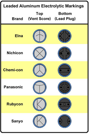
Through-hole capacitors can marking on top
Aluminium electrolytic capacitor lifetime
Aluminum electrolytic capacitors do degrade with time, and this is valid also if you just store them. Many electrolytics have a vent for allowing excess gasses to escape. This escape can result in the electrolyte drying out and the performance of the capacitor falling. Also if aluminum electrolytic capacitors are left for a few years, then the oxide layer on the anode can dissipate. When this happens the capacitor needs to be repolarised. This can be done by applying a current-limited voltage to the capacitor - see description in the next paragraph.
The real lifetime estimation of an electrolytic capacitor:
![]()
Where:
- L0 - is the lifetime at nominal ripple and the upper category temperature from datasheet,
- KT - is the temperature factor calculated for the ambient temperature in the place where is mounted the capacitor,
- KR - is the ripple current factor which generated the self-heating,
- KV - is the voltage factor valculated to the operating voltage,
Temperature factor KT follows the industry wide well established "10-degree-rule" -> a drop of the ambient temperature by 10 K doubles the lifetime:
![]()
Where:
- T0 - is the upper category temperature from datasheet,
- Ta - is the ambient temperature in the application ,
Ripple Current estimates the impact of the applied ripple current on the self-heating and in turn on elcap lifetime by the following formula:
![]() where
where ![]()
Where:
- Ia - is the ripple current in the application,
- I0 - is the nominal ripple current at upper category temperature from datasheet,
- DT0 - is the core temperature increase of the elcap, is 5K at T0 = 105°C and 10K at T0 = 85°C,
- Ki - is an empirical safety factor, defined as: for T0=105°C and I>I0 => Ki=4; for T0=105°C and I< I0 => Ki=2; for T0=85°C => Ki=2,
Voltage factor is important just in case of medium and large size kapacitors, where the operational voltage is close to the rated nominal voltage specified in datasheet:
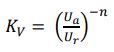
Where:
- Ur - is the rated voltage from the datasheet,
- Ua - is the actual operating voltage,
- n - is an exponent, defined as: 0.5 < Ua/Ur <0.8 => n=3; 0.8 < Ua/Ur < 1.0 => n=5
It is also wise to take precautions to prolong the life of the capacitor. There are four
golden tips to maximize the life of an aluminum electrolytic capacitor:
- Run within its voltage limits,
- Keep within its current rating,
- Never reverse bias the capacitor,
- Keep temperatures down (minimum with less than 10 degrees of its rating).
Reforming aluminium electrolytic capacitors
It may be necessary to re-form electrolytic capacitors that have not been used for six months or more. The electrolytic action tends to remove the oxide layer from the anode and this needs to be re-formed. Under these circumstances, it is not wise to apply the full voltage as the leakage current will be high and may lead to large amounts of heat being dissipated in the capacitor which can in some instances bring about its destruction. To reform the capacitor, the normal method is to apply the working voltage for the capacitor through a resistor of around 1.5 k ohms, or possibly less for lower voltage capacitors. This should be applied for an hour or more until the leakage current drops to an acceptable value and the voltage directly on the capacitor reaches the applied value, i.e. virtually no current is flowing through the resistor. This voltage should then be continued to be applied for a further hour. The capacitor can then be slowly discharged through a suitable resistor so that the retained charge does not cause damage. Once reformed take care when using the capacitor to make sure that it has been fully reformed and is able to function correctly.
Bibliograpfy
- Walter G. Jung and Richard Marsh: Picking Capacitors, Audio, Feb 1980 - the best review and theoretical description of capacitors
- Mark Fortunato: Temp and voltage variation of ceramic caps, or why your 4.7-uF part becomes 0.33 uF
- Carl Pugh: Build your own bypass-capacitor tester
- John Caldwell: Signal distortion from high-K ceramic capacitors and More about understanding the distortion mechanism of high-K MLCCs
- Heinz Dornecker and Bernd M. Engelhard: Selecting and Applying Film Capacitors
- Humble homemade capacitor test. This is a collection of mostly audio-grade capacitors, but don't be disappointed, WIMA (MKP4 and MKP10), Vishay (MKP1837), EPCOS (B32774) has also good sounds - all depends by your budget.
- Do capacitors sound different? - from TNT Audio
- How to Test Capacitor Without Desoldering - In-circuit Testing Guide by Yaman
- Distrelec homepage - a big electronic components supplier, from their page I downloaded all pictures about capacitors.
- Electrolytic Capacitor Lifetime Estimation - written by Dr. Arne Albertsen. This article outlines the construction of elcaps and explains related terms like ESR, ripple current, self-heating, chemical stability, and lifetime. Two estimation tools for obtaining elcap lifetime approximations in an application are introduced and illustrated by an example - I used it in the above presented electrolytic capacitors lifetime calculation.