B5 - an excelent AB class amplifier
This amplifier was designed by 'KD mester', and I meet firstly the schematic on AudioDIY forum - now that topic has more than 20 pages, but just in Hungarian. Later I found a good decscription made by the author (also in Hungarian) on Hobbielektronika webpage and on its forum with more than 14 pages! In both forums anybody, who already built is/heard it, was very impressed about the sound of this amplifier - that was the reason I also built it.
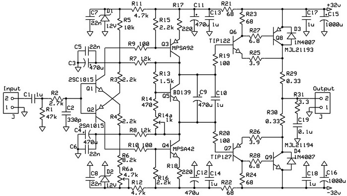
Figure 1 B5 amplifier schematic - my version (with extra capacitors)
'KD mester' really designed a good amplifier, which can be compared with any industrial high-end product, with good and listenable sound without any coloration.
The schematic can be seen in Figure 1. Is a symmetrical design without overall negative feedback, but several local feedbacks ensuring the high linearity. Such topology is used by high-end amplifier manufacturers, like Hungarian Etalon.
The power stage is made by triple-Darlington, formed by Q6-Q8 and Q7-Q9 (TIP122 and TIP127 are Darlington transistors), to decrease the negative effect on voltage amplifiers high impedance output caused by power transistors distorted base current. For that reason, the input resistance of the power stage will be high with high linearity, and easy to be driven.
The author remarks the components must be the same as he indicated because that gives the best results, tested with the long listening experience. He highly recommends being used especially the same type of power transistors (MLJ21193 and MLJ21194)! Basically, I changed just the differential input stage, instead of BC546/BC556 I use 2SA1015/2SC1815, for the latest was designed the PCB, but after I changed them back to BC546/BC556 original Philips, because they sound better. Please note, the 2SA1015/2SC1815 are not pin-compatible with BC546/BC556!
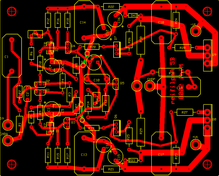
Figure 2 The pcb of B5 amplifier from Figure 1.
Figure 3 The final PCB - with already soldered components.
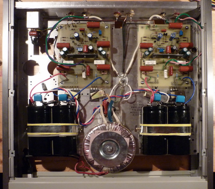
Figure 4 The final stereo B5 amplifier - inside
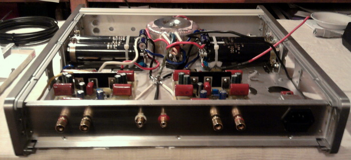
Figure 5 The back side with input and output connectors (picture was made during construction, right side apmlifier is not connected, and now I use different capacitors - see previous picture).
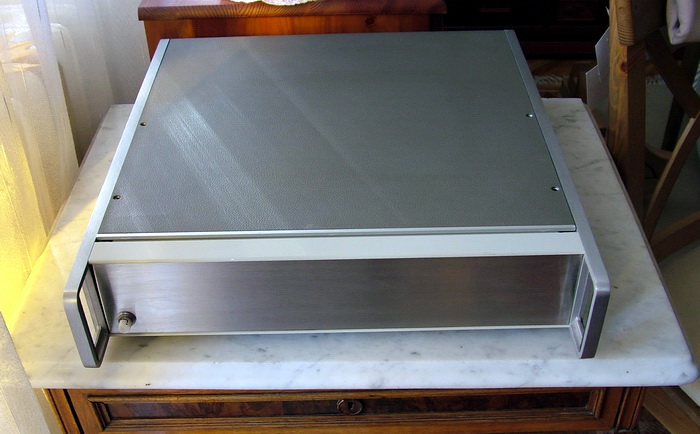
Figure 5 The final amplifier.